Cutting insert for high-speed milling cutter

a cutting insert and high-speed technology, which is applied in the direction of cutting inserts, shaping cutters, manufacturing tools, etc., can solve the problems of inserts being unseated from the insert pocket, the development of a milling cutter capable of operating, and the substantial increase in the centrifugal force generated on the inserts of the cutter

Active Publication Date: 2006-01-19
KENNAMETAL INC
View PDF12 Cites 43 Cited by
  • Summary
  • Abstract
  • Description
  • Claims
  • Application Information

AI Technical Summary

Benefits of technology

[0010] The inventors of the present invention have recognized these and other problems associated with high-speed milling cutters and associated cutting inserts. Briefly, according to this invention, there is provided an indexable cutting insert for a high-speed, long edge milling cutter. As used herein the term “long edge milling cutter” refers to a milling cutter utilizing an insert having a cutting edge greater than about ⅝ of an inch. The cutting insert includes a top surface having a substantially planar central portion, a substantially planar bottom surface, and a plurality of side surfaces; one side surface including a flat surface extending from the bottom surface and a margin extending from the top surface to the flat surface; a long cutting edge defined at an intersection between the top surface and the margin of one of the side surfaces; a corner radius cutting edge defined at an intersection between the top surface and one of the side surfaces; a facet radius cutting edge defined at an intersection between the top surface and one of the side surfaces; and a ramping cutting edge defined at the intersection between the top surface and one of the side surfaces. The margin extends around a nose radius of the cutting insert and blends into the flat surface. The margin angle formed by the margin is less than a seating angle formed by the flat surface.
[0011] In another aspect of the invention, a high-speed, long edge milling cutter includes a shank having an insert pocket, and at least one indexable cutting insert having a top surface having a substantially planar central portion, a substantially planar bottom surface, and a plurality of side surfaces; one side surface including a flat surface extending from the bottom surface and a margin extending from the top surface to the flat surface; a long cutting edge defined at an intersection between the top surface and the margin of one of the side surfaces; a corner radius cutting edge defined at an intersection between the top surface and one of the side surfaces; a facet radius cutting edge defined at an intersection between the top surface and one of the side surfaces; and a ramping cutting edge defined at the intersection between the top surface and one of the side surfaces. The margin extends around a nose radius of the cutting insert and blends into the flat surface. The margin angle formed by the margin is less than a seating angle formed by the flat surface.

Problems solved by technology

The fact that the centrifugal force (and hence tensile stress) on the cutter body increases with the square of the angular velocity has, up to now, posed a substantial obstacle in the development of a milling cutter capable of operating at speeds higher than several thousand rpm.
In addition, the substantial increase in rotational speed necessary to obtain all the aforementioned advantages also results in a substantial increase in the centrifugal forces generated on the inserts of the cutter.
Specifically, the centrifugal forces tend to cause the inserts to become unseated from the insert pocket during high-speed milling operations.
These systems are quick to clog if the shape and / or size of the chips are not controlled to manageable levels.

Method used


Image

  • Cutting insert for high-speed milling cutter
  • Cutting insert for high-speed milling cutter
  • Cutting insert for high-speed milling cutter

Examples


Embodiment Construction

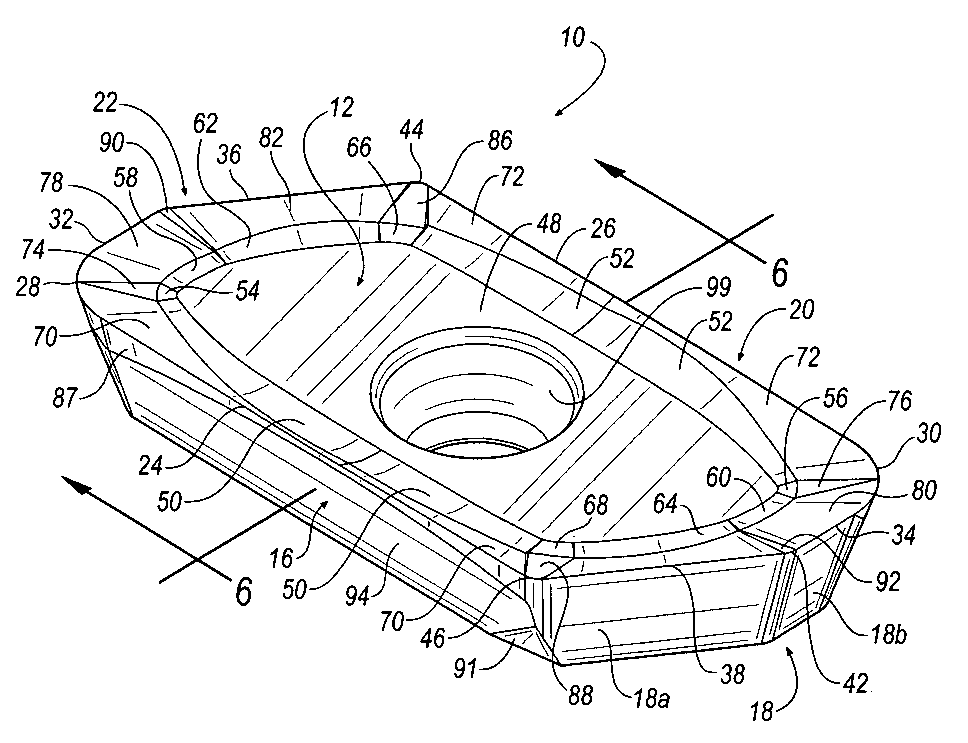
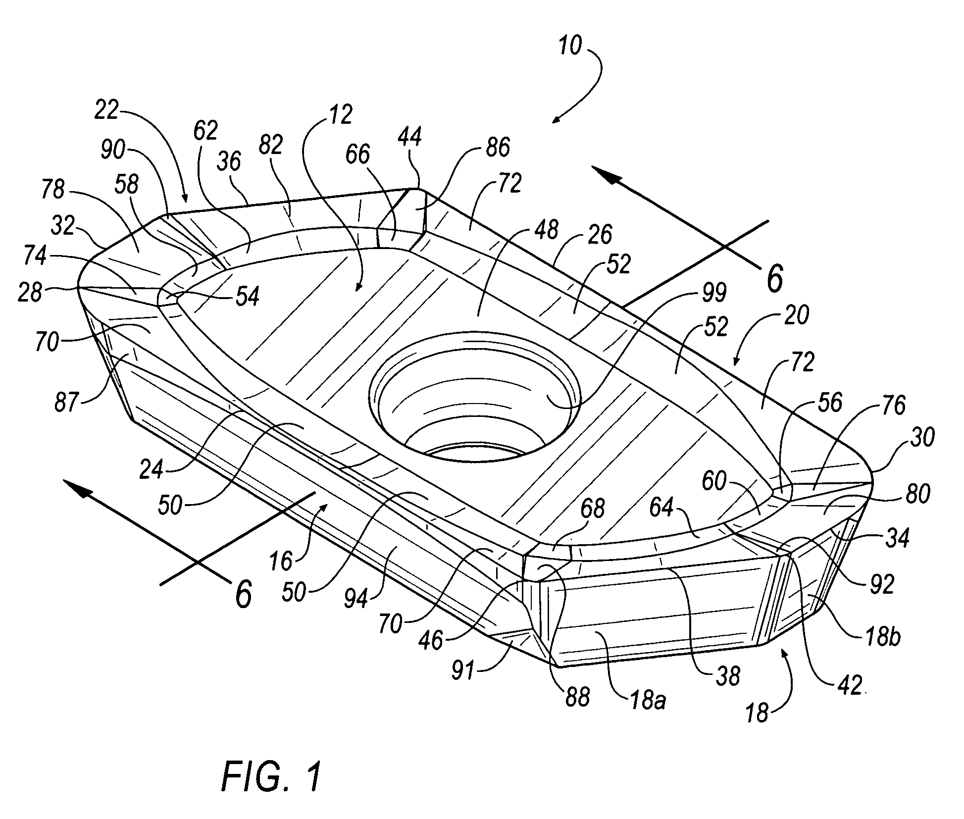
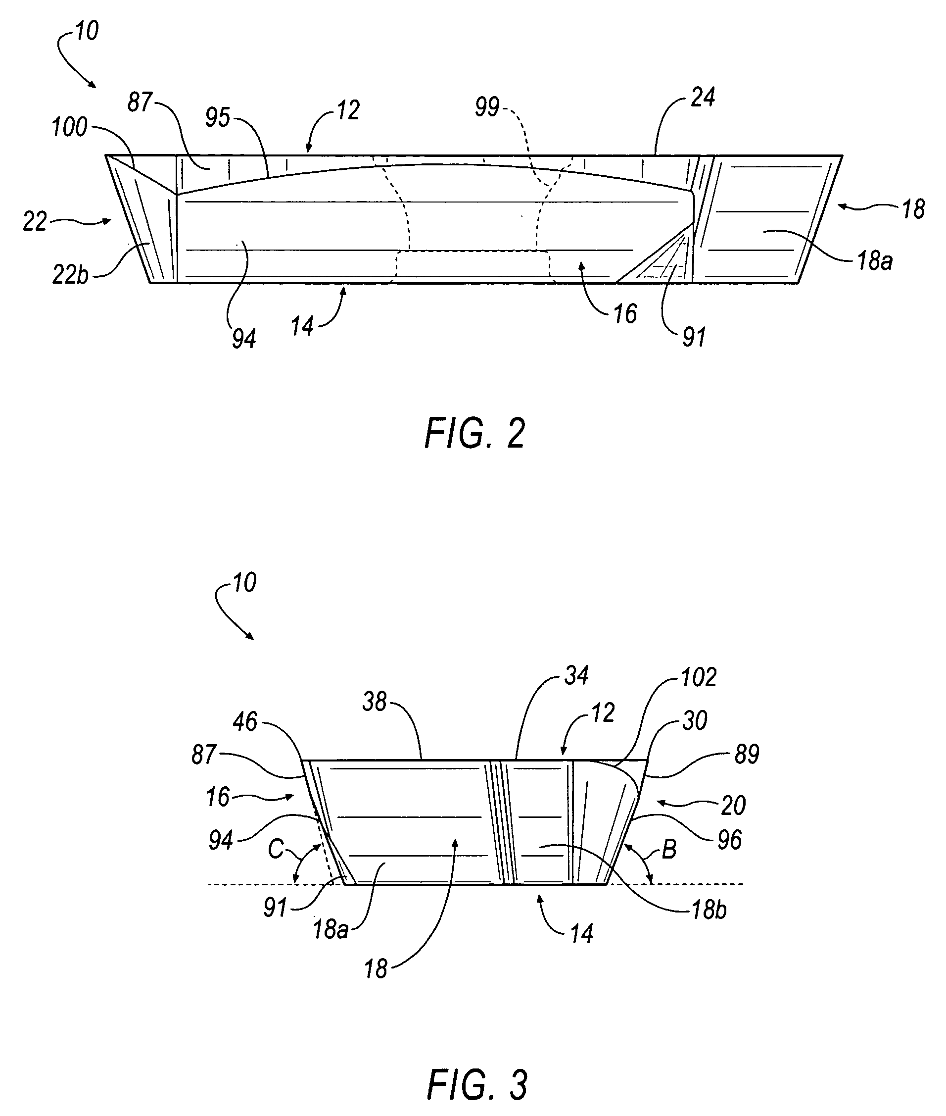
[0020] Referring to FIGS. 1-6, wherein like reference characters represent like elements, an indexable cutting insert 10 includes generally, a top surface 12, a bottom surface 14 and side surfaces 16, 18, 20, 22.

[0021] The side surface 18 is further comprised of a first side surface 18a, and a second side surface 18b that is angled less than ninety (90) degrees with respect to the first surface 18a. Similarly, side surface 20 is further comprised of sides surfaces 20a, 20b that are also angled with respect to each other. First or long cutting edges 24, 26 are defined at the intersections between the top surface 12 and the side surfaces 16, 20, respectively. Second or corner radius cutting edges 28, 30 are defined generally at the intersections between the top surface 12 and the side surfaces 16, 18, 20 and 22. Specifically, the corner radius cutting edge 28 is defined generally at the intersection of side surfaces 16, 22, and the corner radius cutting edge 30 is defined generally a...


PUM

PropertyMeasurementUnit
angleaaaaaaaaaa
angleaaaaaaaaaa
angleaaaaaaaaaa

Abstract

An indexable cutting insert (10) having a top surface (12) including a substantially planar central portion (48), a substantially planar bottom surface (14), and a plurality of side surfaces (16, 18, 20, 22). A long cutting edge (24, 26), a corner radius cutting edge (28, 30), a facet radius cutting edge (32, 34), and ramping cutting edge (36, 38) are defined at an intersection between the top surface (12) and one of the side surfaces (16, 18, 20, 22). A margin (87, 89) extends around a nose radius of the cutting insert (10) and blends into a flat surface (94, 96). A margin angle, C, formed by the margins (87, 89) is less than a seating angle, B, formed by the flat surfaces (94, 96). The top surface (12) includes a plurality of upward sloping radius blends (50, 52, 54, 56, 58, 60, 62, 64) extending between the substantially planar central portion (48) and a plurality of upward sloping rake faces (70, 72, 74, 76, 78, 80, 82, 84, 86, 88, 90, 92) extending between a respective radius blend and its respective cutting edge such that the rake face forms an angle, A, of between five and twenty-five degrees with respect to the central portion (48) of the top surface (12).

Description

CROSS-NOTING TO RELATED APPLICATION [0001] This application is related to U.S. patent application Ser. No. 10 / 754,825, filed Jan. 9, 2004, entitled “High-Speed Milling Cutter and Insert”, the entire contents of which are incorporated herein by reference.BACKGROUND OF THE INVENTION [0002] 1. Field of the Invention [0003] This invention relates to a cutting insert for a high-speed milling cutter. More particularly, this invention relates to an indexable cutting insert for a long edge, high-speed milling cutter for milling a metallic work piece, such as aluminum, or the like. [0004] 2. Description of the Related Art [0005] Milling cutters for performing machining operations on metallic work pieces are well known in the prior art. Such cutters typically comprise a cylindrical or disc-shaped body which is detachably connectable to a rotating drive shaft. A plurality of cutting inserts are mounted around the outer periphery of the cutter body for producing a series of metal-shaving cuts o...

Claims


Application Information

Patent Timeline
Patent Type & Authority Applications(United States)
IPC IPC(8): B23B27/16
CPCB23B27/1622Y10T407/24B23B2200/3618B23B2220/36B23C5/109B23C5/2221B23C2200/0438B23C2200/125B23C2200/201B23C2200/361B23C2200/365B23C2220/44Y10T407/23Y10T407/235Y10T407/245B23B2200/201B23C2200/286B23C2210/045B23C2210/0457B23C5/2213B23C5/20B23B27/16
Inventor LONG, THOMAS J. IIFRYE, SHAWN E.CRAIG, KAREN A.
Owner KENNAMETAL INC
Why Eureka
Try Eureka