
Golf club head structure for improving casting fluidity in a slurry shell

a golf club and slurry shell technology, which is applied in the field of golf club head structure for improving casting fluidity in slurry shell, can solve the problems of unsuitable golf club head casting, limited application scope of fe—mn-al alloy in the industry, and difficulty in eliminating contraction cavities by means of finishing grinding process, etc., and achieves the effect of improving casting fluidity

Inactive Publication Date: 2006-01-19
HOU WEN CHING
View PDF5 Cites 5 Cited by
  • Summary
  • Abstract
  • Description
  • Claims
  • Application Information

AI Technical Summary

Benefits of technology

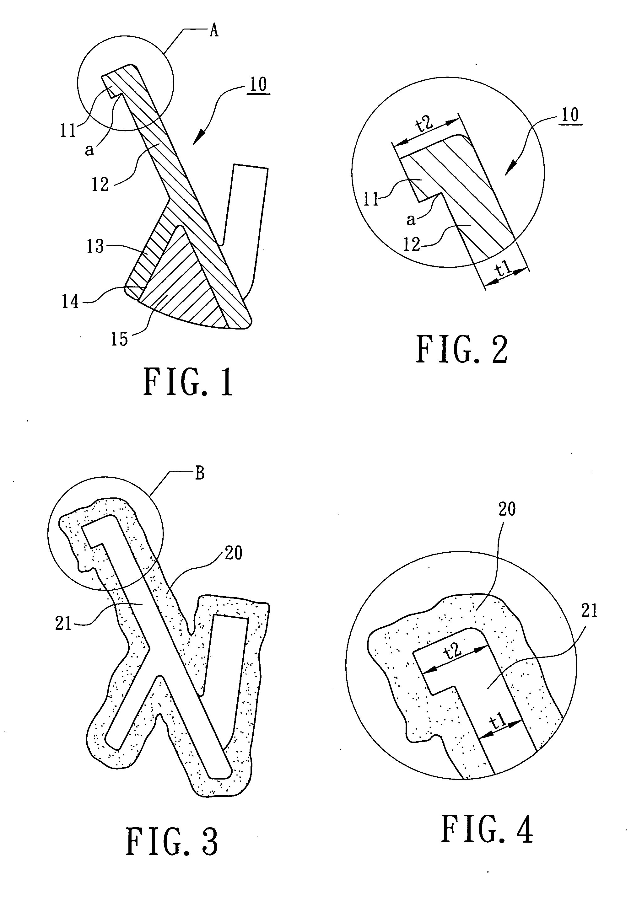
[0006] The primary objective of this invention is to provide a golf club head structure for improving casting fluidity in a slurry shell. The golf club head structure consists of two adjacent portions having changes in thickness corresponding to changes in width of the slurry shell to thereby avoid generating contraction cavities and slag-eyes in a casting.
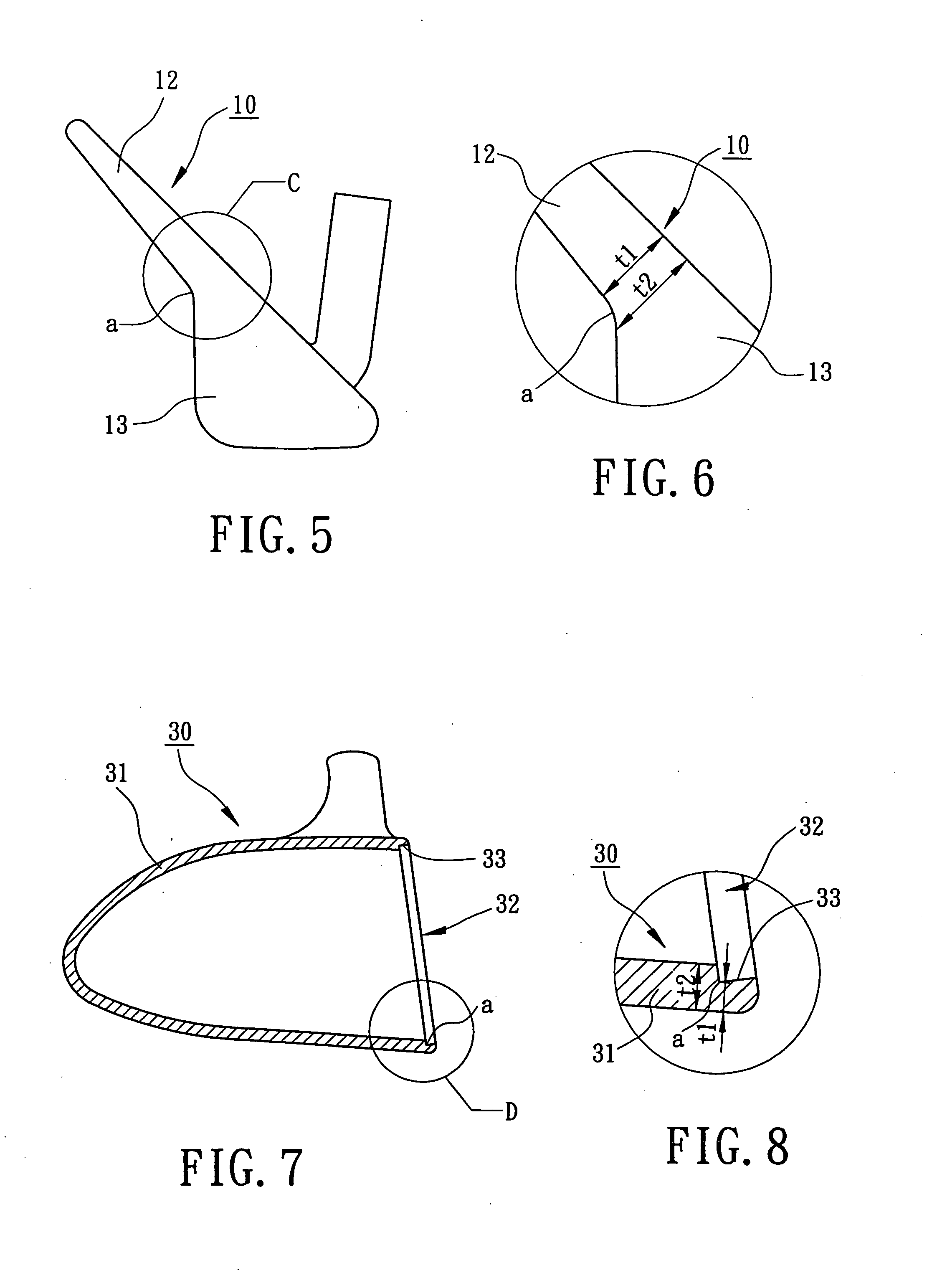
[0007] The golf club head structure in accordance with the present invention includes a first portion and a second portion adjacent thereto. The first portion and the second portion have a first thickness and a second thickness respectively. The ratio of the first thickness to the second thickness ranges between 0.56 and 1.00 that may enhance casting fluidity of molten iron in a slurry shell to thereby reduce the possibility of generating contraction cavities and slag-eyes in the golf club head.

Problems solved by technology

In slush casting, inevitably, when Fe—Mn—Al alloy is employed to cast a casting of a golf club head, a finished product of the casting has many casting deficiencies of cold-shot, contraction cavities and slag-eye due to low casting fluidity in a slurry shell.
However, when the contraction cavities are located in a complicated structure and an unbalanced thickness (such as an opening or an undercut) of the golf club head, it is hard to eliminate the contraction cavities by means of the finishing and grinding process.
Consequently, the contraction cavities may be remained on the surface of the golf club head that may result in a decrease in the value of products.
Thus, the applied scope of Fe—Mn—Al alloy in the industry is restricted and unsuitable for casting the golf club head.

Method used


Image

  • Golf club head structure for improving casting fluidity in a slurry shell
  • Golf club head structure for improving casting fluidity in a slurry shell
  • Golf club head structure for improving casting fluidity in a slurry shell

Examples


Embodiment Construction

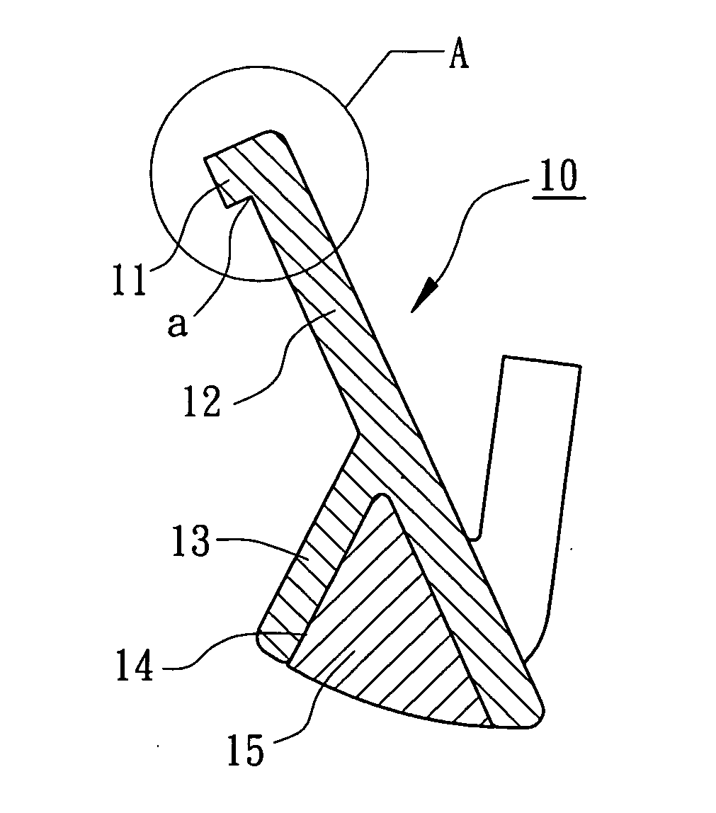
[0018] Referring initially to FIGS. 1 through 4, a golf club head structure in accordance with a first embodiment of the present invention includes a club head body 10 pertaining to an iron-type club head integrally formed with a single member and made of Fe—Mn—Al alloy. The single member of the club head body 10 includes an annular flange 11, a flat plate portion 12, a weight portion 13 and a compartment 14. In assembling, the compartment 14 is adapted to receive a weight member 15 for adjusting a center of gravity of the club head body 10. Each of the club head sections has two adjacent portions gradually changing in thickness, a connecting portion of the flat plate portion 12 to the annular flange 11 or the flat plate portion 12 to the weight portion 13 for example.

[0019] Referring again to FIG. 3, a slurry shell 20 can be made by dewaxing a wax pattern (not shown) of the club head body 10. The construction of the slurry shell 20 has a cavity 21 configured with an inner space co...


PUM


Abstract

A golf club head structure includes a first portion and a second portion adjacent thereto. The first portion and the second portion have a first thickness and a second thickness respectively. The ratio of the first thickness to the second thickness ranges between 0.56 and 1.00 that may enhance casting fluidity of molten iron in a slurry shell to thereby reduce the possibility of generating contraction cavities and slag-eyes in the golf club head.

Description

BACKGROUND OF THE INVENTION [0001] 1. Field of the Invention [0002] The present invention relates to a golf club head structure for improving casting fluidity in a slurry shell. More particularly, the present invention relates to a golf club head structure consisting of two adjacent portions having changes in thickness to improve casting fluidity in a slurry shell and casting quality. [0003] 2. Description of the Related Art [0004] Fe—Mn—Al alloy has highly low density, excellently vibration-absorbable and high degree of hardness. Casting a golf club head with Fe—Mn—Al alloy, the center of gravity of the golf club head may be lowered, and a striking surface area and dimensions of the golf club head may be increased. In slush casting, inevitably, when Fe—Mn—Al alloy is employed to cast a casting of a golf club head, a finished product of the casting has many casting deficiencies of cold-shot, contraction cavities and slag-eye due to low casting fluidity in a slurry shell. Generally, ...

Claims


Application Information

Patent Timeline
Patent Type & Authority Applications(United States)
IPC IPC(8): A63B53/04
CPCA63B53/04A63B2053/0416A63B53/047A63B53/0466A63B2053/0433A63B2053/0491A63B53/0416A63B53/0433A63B60/00
Inventor HOU, WEN-CHING
Owner HOU WEN CHING
Learn More