Waferless fiber Fabry-Perot filters

a fabryperot filter and fiber technology, applied in the field of fabryperot, can solve the problems of reducing stability and optical performance, limiting the fsr that can be achieved, and prone to mechanical and thermal instabilities, so as to reduce alignment sensitivity and minimize light loss.

Active Publication Date: 2005-06-07
LUNA INNOVATIONS
View PDF135 Cites 18 Cited by
  • Summary
  • Abstract
  • Description
  • Claims
  • Application Information

AI Technical Summary

Benefits of technology

[0029]Contour profiles of the present invention may be continuous surfaces or discontinuous surfaces. Alternatively, contour profiles useable in the present invention may be characterized by both continuous regions and discontinuous regions. Contour profiles useable in the present invention may be substantially symmetrical about an axis, such as the fiber axis or the optical axis of the resonance cavity. In embodiments of the present invention providing minimized light loss in the resonance cavity and decreased alignment sensitivity, deviations from absolute symmetry about the fiber axis is less than 10% and more preferably less than 5%. Alternatively, the present invention includes embodiments having contour profiles which are asymmetrical with respect to an axis, such as a fiber axis or the optical axis of a resonance cavity.

Problems solved by technology

The expanded beam size of such a filter results in reduced stability and optical performance, and also limits the filter FSR that can be achieved.
A MEMS-FP filter uses curved and suspended dielectric mirrors, and as a result tends to suffer from mechanical and thermal instabilities.
However, due to the high precision requirements for making a wafer or waveguide of selected length, it becomes very difficult to fabricate wafered cavity filters with wide-FSR (>100 nm).
In addition to the difficulties inherent in the reproducible manufacture of fiber wafers of short and precise length, the beam shaping effect of the wafer decreases with its length and as a result filters having such short wafers can exhibit high sensitivity to alignment offset.
Decrease in manufacturing yield due to machining imperfections and difficulty with fiber alignment makes production of wafered FFP filters for applications requiring a FSR greater than about 100 nm impractical.

Method used


Image

  • Waferless fiber Fabry-Perot filters
  • Waferless fiber Fabry-Perot filters
  • Waferless fiber Fabry-Perot filters

Examples


Embodiment Construction

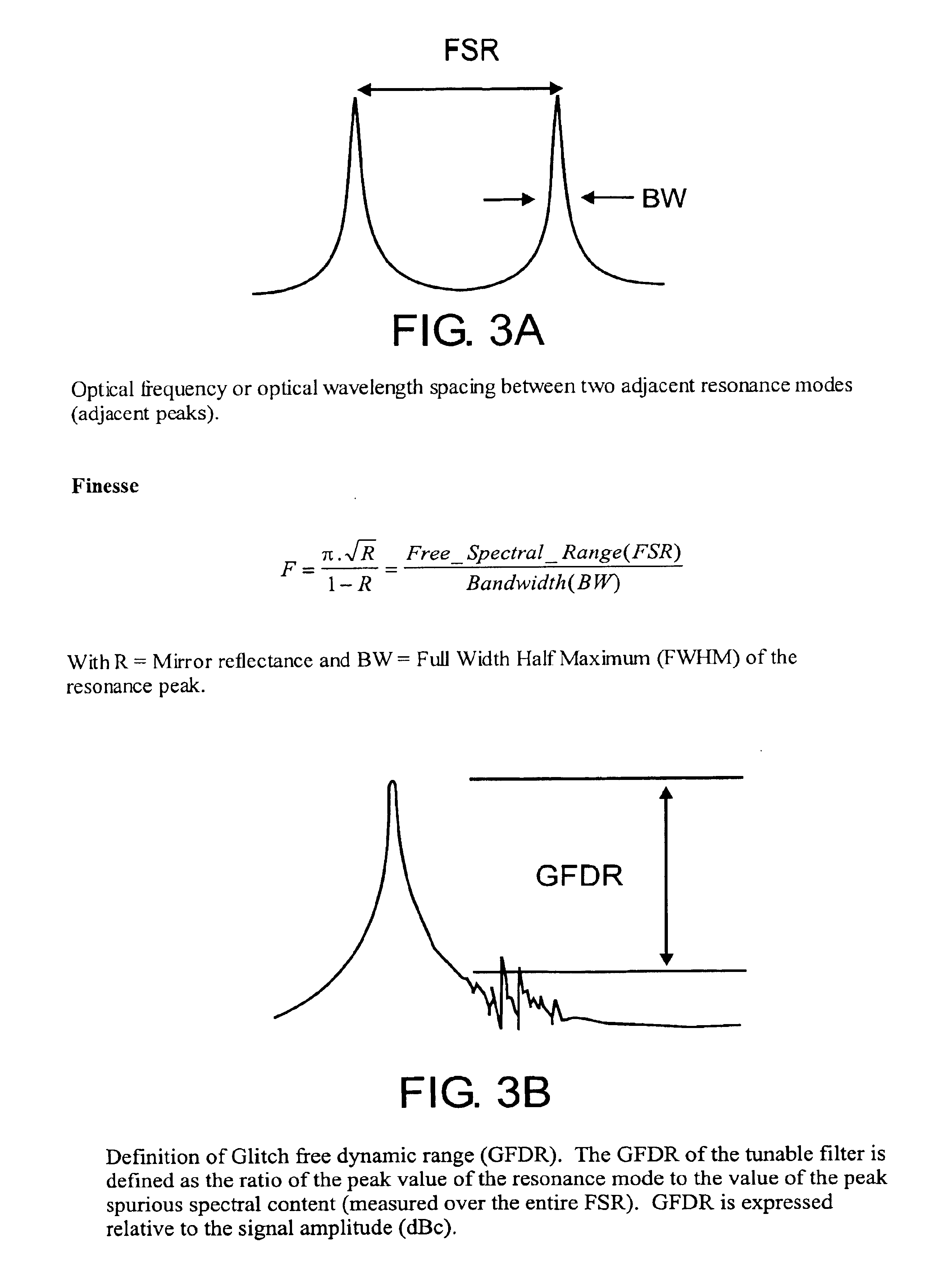
[0043]The terms free spectral range, bandwidth and finesse are used generally as they are used in the art. FIG. 3A illustrates the definitions of these terms in an exemplary spectrum. Those of ordinary skill in the art will appreciate that the definitions of these terms may depend on the shape of the peaks in the spectral output of the filter.

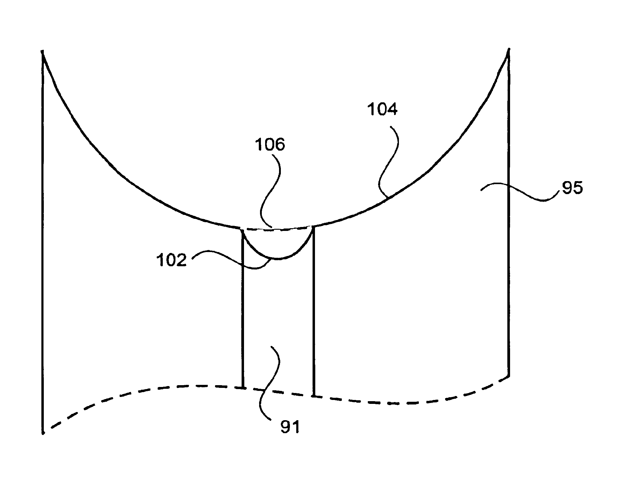
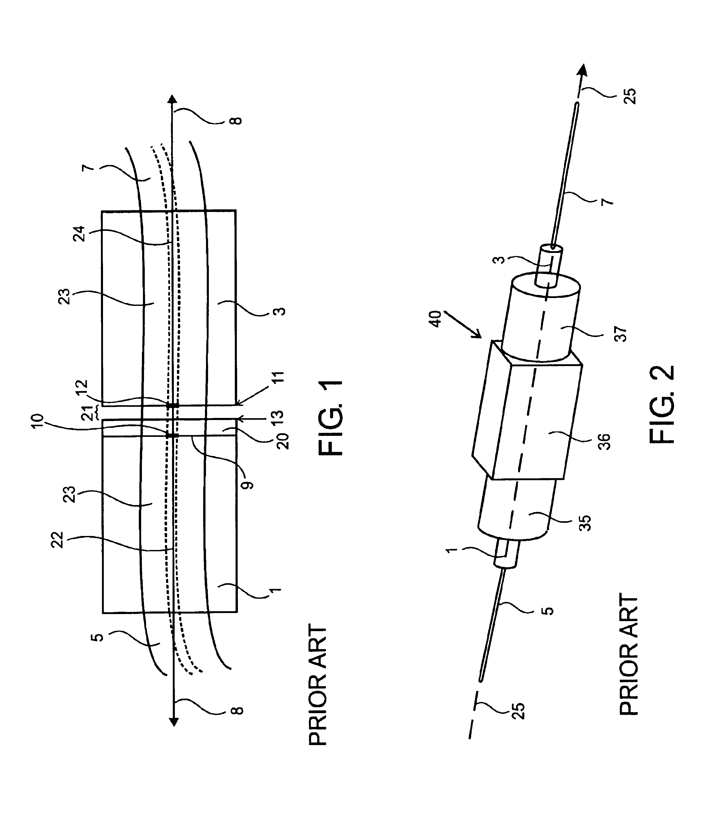
[0044]For descriptions herein an optical fiber has an internal end face and an external end. The internal end is the fiber end that is closest to the fiber gap within the FFP cavity. Thus, two internal fiber ends are aligned and spaced apart to form the gap within the FFP. A fiber contains a substantially axial longitudinal core surrounded by a cladding layer. Fiber Fabry-Perot filters of this invention are formed between mirrors at the internal ends of two fibers, between a mirror embedded between two fiber ends and one at an internal fiber end or between two embedded mirrors. Mirrors are typically formed at fiber ends by deposition of one or ...


PUM


Abstract

Improved fiber Fabry-Perot (FFP) filter configurations are provided in which at least one of the mirror-ended fiber ends forming the FFP has a concave fiber core end. The mirror at that fiber core end is thus concave. The invention provides waferless FFP configurations in which the FFP cavity is an air-gap cavity formed by two highly reflective dielectric mirrors deposited directly on optical fiber ends. The air gap cavity can be tuned using various methods to tune the filter. Use of a concave mirror at the fiber core enables filters with improved performance characteristics: including very wide FSR (>12000 GHz), very high finesse (>5,000), and high glitch-free dynamic range (GFDR) (>40 dB). The invention also provides improved wafer-based FFP fixed and tunable filters that incorporate a concave mirror at a fiber core forming the FFP cavity and a fiber (SMF) waveguide within the cavity.

Description

CROSS-REFERENCE TO RELATED APPLICATIONS[0001]This application claims priority under 35 U.S.C. 119(e) to provisional patent application 60 / 418,767, filed Oct. 15, 2002, which is hereby incorporated by reference in its entirety to the extent not inconsistent with the disclosure herein.BACKGROUND OF THE INVENTION[0002]A Fabry-Perot (FP) filter is made of a pair of mirrors separated by a selected optical path length which form the resonance cavity of the filter. A FP filter passes a narrow band of light determined by the reflectivities of its mirrors which satisfy a resonance condition such that when the optical length of the round-trip length of the cavity is an integer of a wavelength, then that wavelength together with a narrow band resonates inside the cavity, and passes through the filter with no (theoretically) or very low loss.[0003]For a fixed FP cavity length, the resonant wavelength changes periodically. The period of the resonant wavelength is called free spectral range (FSR)...

Claims


Application Information

Patent Timeline
Patent Type & Authority Patents(United States)
IPC IPC(8): G02B6/26G02B6/34H01S
CPCG02B6/262G02B6/29395G02B6/29359
Inventor BAO, YUFEIFERGUSON, STEPHEN K.SNYDER, DONALD Q.
Owner LUNA INNOVATIONS
Why Eureka
Try Eureka