Transobturator introducer system for sling suspension system

a technology of introducer system and introducer needle, which is applied in the field of transobturator introducer system for sling suspension system, can solve the problems of unpractical method, unpractical use of existing introducer needle, and unwieldy implant placement, etc., and achieves the effect of convenient needle insertion, easy insertion of the implant, and more visualization control

Active Publication Date: 2006-01-19
CR BARD INC
View PDF95 Cites 50 Cited by
  • Summary
  • Abstract
  • Description
  • Claims
  • Application Information

AI Technical Summary

Benefits of technology

[0020] In another embodiment of the invention, an introducer needle is provided, that is shaped in a horseshoe shaped halo design. This design can enable easier insertion of the implant within the body by allowing the doctor more visualization control of holding and navigating the needle.
[0021] In one embodiment of the invention, a needle tip is provided, in which the tip of the needle has a diameter that is smaller than the inner diamete

Problems solved by technology

A deficiency with existing introducer devices, however, is that they are typically unwieldy, awkward and time consuming to attach and/or detach to an implant to or from an introducer device.
Another deficiency with existing introducer systems is that, in performing certain procedures, such as a transobturator needle inside-out approach in which the needle is first inserted and then passed through the obturator foramen, the use of existing introducer needles is commonly not practical because once in an earlie

Method used


Image

  • Transobturator introducer system for sling suspension system
  • Transobturator introducer system for sling suspension system
  • Transobturator introducer system for sling suspension system

Examples


Embodiment Construction

[0120] Referring now to the drawings, the various preferred embodiments of the present invention will be discussed in detail.

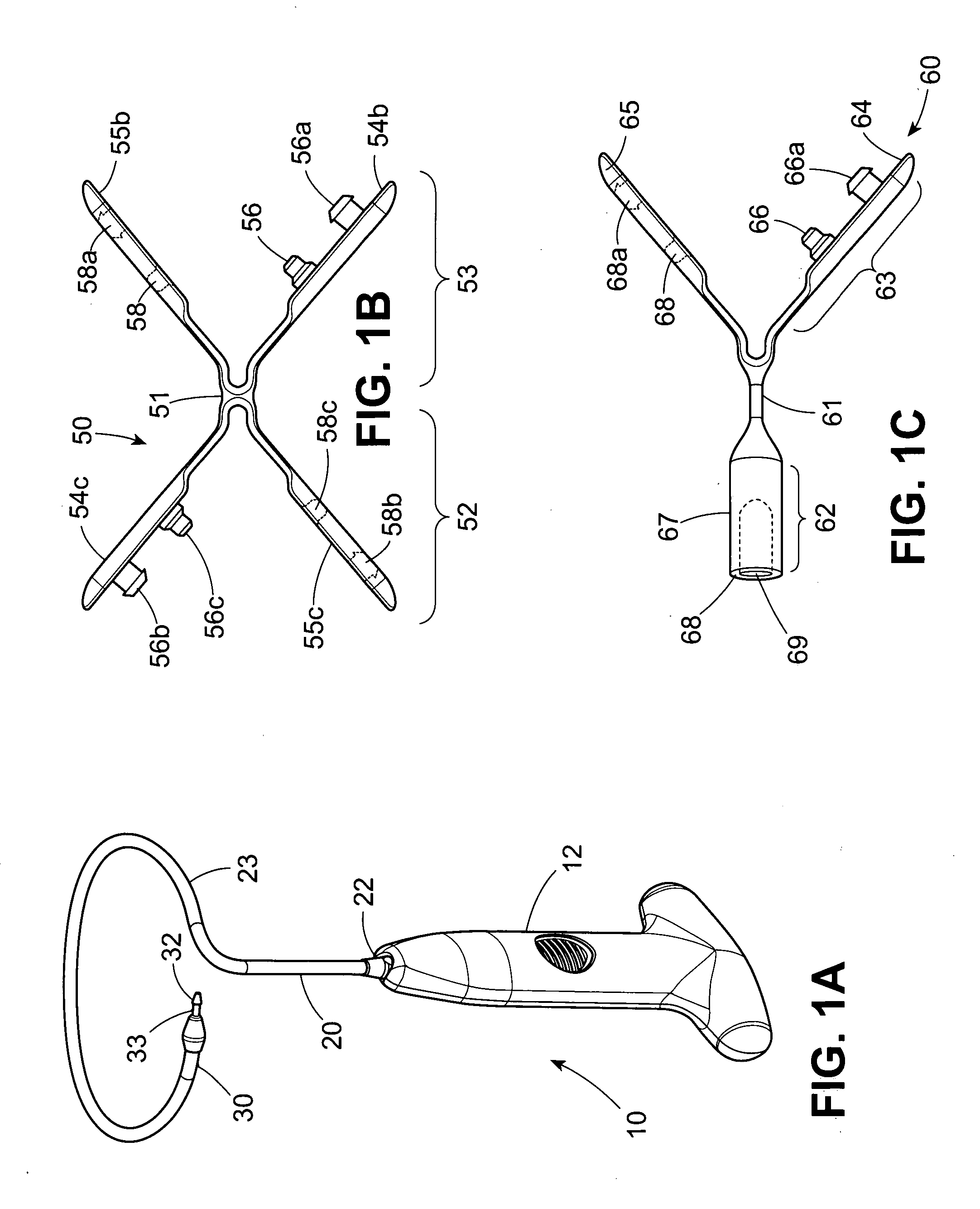
[0121] As depicted in FIG. 1A an introducer device 10 is shown in accordance with an embodiment of the invention. As is discussed in further detail below, introducer device 10 may be used to introduce an implant strip, such as, for example, a tissue implant, into a patient. Introducer device 10 comprises an introducer handle 12 which is shown attached to an introducer needle 20. Introducer needle 20 may be permanently attached to introducer handle 12 or, as is discussed in further detail below, introducer needle 20 can be selectively detachably connected to introducer handle 12. Introducer needle 20 can have a curved portion 23, and, located at a proximal end 30 of introducer needle 20, a shaft portion 33 and a barb 32. As will be discussed in further detail below, curved portion 23 of introducer needle 20 allows a doctor to insert an implant strip or tissue ...


PUM


Abstract

An introducer device comprising: an introducer needle having a proximal end and a distal end and a handle having a needle receiving end. The handle can be adapted to receive said distal end of said introducer needle such that said introducer needle is selectably detachably coupled to said handle. A connector for attachment to an implant strip can have an arm having a hole therethrough and an introducer needle including a connection portion having a barb. It can comprise a central portion; a first arm pivotally mounted to the central portion and having a first projection and a second projection extending therefrom. A second arm can be pivotally mounted to the central portion and having a first hole and a second hole defined therein. The first and second holes can be positioned so that when the first arm pivots toward the second arm, the first and second projections are received in the first and second holes. A tube portion can extend from said central portion and define a tube aperture therein. The tube aperture can be adapted to receive the barb such that the connector can be selectably detachably coupled or permanently affixed to the introducer needle.

Description

CROSS REFERENCE TO RELATED APPLICATIONS [0001] This application is a continuation-in-part of, U.S. application Ser. No. 10 / 633,254 filed on Aug. 1, 2003, for SELF-ANCHORING AND INTRODUCER SYSTEM, which claims the benefit of U.S. Provisional Application No. 60 / 479,039 filed on Jun. 17, 2003 for EXPANDABLE TISSUE SLING AND METHOD OF FORMING THE SLING and U.S. Provisional Application No. 60 / 400,616, filed on Aug. 2, 2002, for NATURAL TISSUE SELF-ANCHORING SLING AND INTRODUCER SYSTEM, all of which are hereby incorporated herein by reference. This application also claims the benefit of U.S. Provisional Application No. 60 / 578,552, for SLING SUSPENSION SYSTEM filed on Jun. 9, 2004, which application is hereby incorporated by reference herein.BACKGROUND OF THE INVENTION [0002] An increasingly widespread technique for treating female urinary incontinence is that of sling suspension. Examples of such procedures and equipment which can be employed are discussed in U.S. Pat. Nos. 5,112,344, 5,8...

Claims


Application Information

Patent Timeline
IPC IPC(8): A61M5/178A61B17/00A61BA61B1/00A61B17/04A61B17/06A61B17/08A61F2/00A61F2/02A61F5/48A61L31/00A61M37/00
CPCA61B17/06066A61B17/06109A61B2017/0046A61B2017/00805A61F2220/0016A61B2017/06076A61B2017/06085A61B2017/0609A61F2/0045A61B2017/06009
Inventor EVANS, DOUGLAS G.BUTCHER, KENKNAPP, TRACEY
Owner CR BARD INC
Why Eureka
Try Eureka