Conveyor assembly

a technology of conveyors and components, applied in the direction of conveyor parts, rollers, rollers, etc., can solve the problems of difficult cleaning unsuitable for use in clean room environments, and difficult maintenance of known conveyors or drive mechanisms, so as to reduce the risk of damage to manufactured goods, the effect of sufficiently cleaning

Inactive Publication Date: 2006-01-26
ACTIVAR TECHN PRODS GROUP
View PDF10 Cites 17 Cited by
  • Summary
  • Abstract
  • Description
  • Claims
  • Application Information

AI Technical Summary

Benefits of technology

[0007] It is a principle advantage of the present invention to provide a conveyor formed of relatively simple and inexpensive components and design which fulfills the intended purpose of being sufficiently clean for use with in a clean room which simultaneously fulfills the intended purpose of functioning as a conveyor while minimizing the risk of damage to manufactured goods.
[0008] Another principle advantage of the present invention is to provide a conveyor having a recessed pocket containing motor components.
[0009] It is still another principle advantage of the present invention to provide a conveyor having a motor stator fixedly attached to a structural rail.
[0010] It is still another principle advantage of the present invention to provide a circuit board connected to the motor stator.
[0011] It is still another principle advantage of the present invention to provide a motor rotor comprising alternating magnetic pole portions disposed in a generally circumferential housing arranged about the motor stator.
[0012] Still another principle advantage of the present invention is a provision of a motor rotor used as the conveying roller surface.

Problems solved by technology

The use of these types of drive mechanisms generally require relatively large conveyors or structures.
In addition, the known types of conveyors or drive mechanisms are difficult to keep clean, as the belts, chains, and / or shaft drive mechanisms frequently accumulate dirt and / or become soiled during use.
The known conveyor systems generally are undesirable for use within a clean room environment.
Frequently, clean room specifications are incompatible and do not tolerate the level of dirt and discharged particles associated with the use of a conventional conveyor.
Typically, a business having a clean room is required to forgo use of a conveyor within that room due to the cleanliness issues.
Further, clean rooms are expensive and have a high cost per unit area.
A clean room within a business is preferably of moderate size, and therefore not readily amendable to the use of a relatively large conventional conveyor structure.

Method used


Image

  • Conveyor assembly
  • Conveyor assembly
  • Conveyor assembly

Examples


Embodiment Construction

[0035] While this invention may be embodied in many different forms, there are described in detail herein specific preferred embodiments of the invention. This description is an exemplification of the principles of the invention and is not intended to limit the invention to the particular embodiments illustrated.

[0036] For the purposes of this disclosure, like reference numerals in the figures shall refer to like features unless otherwise indicated.

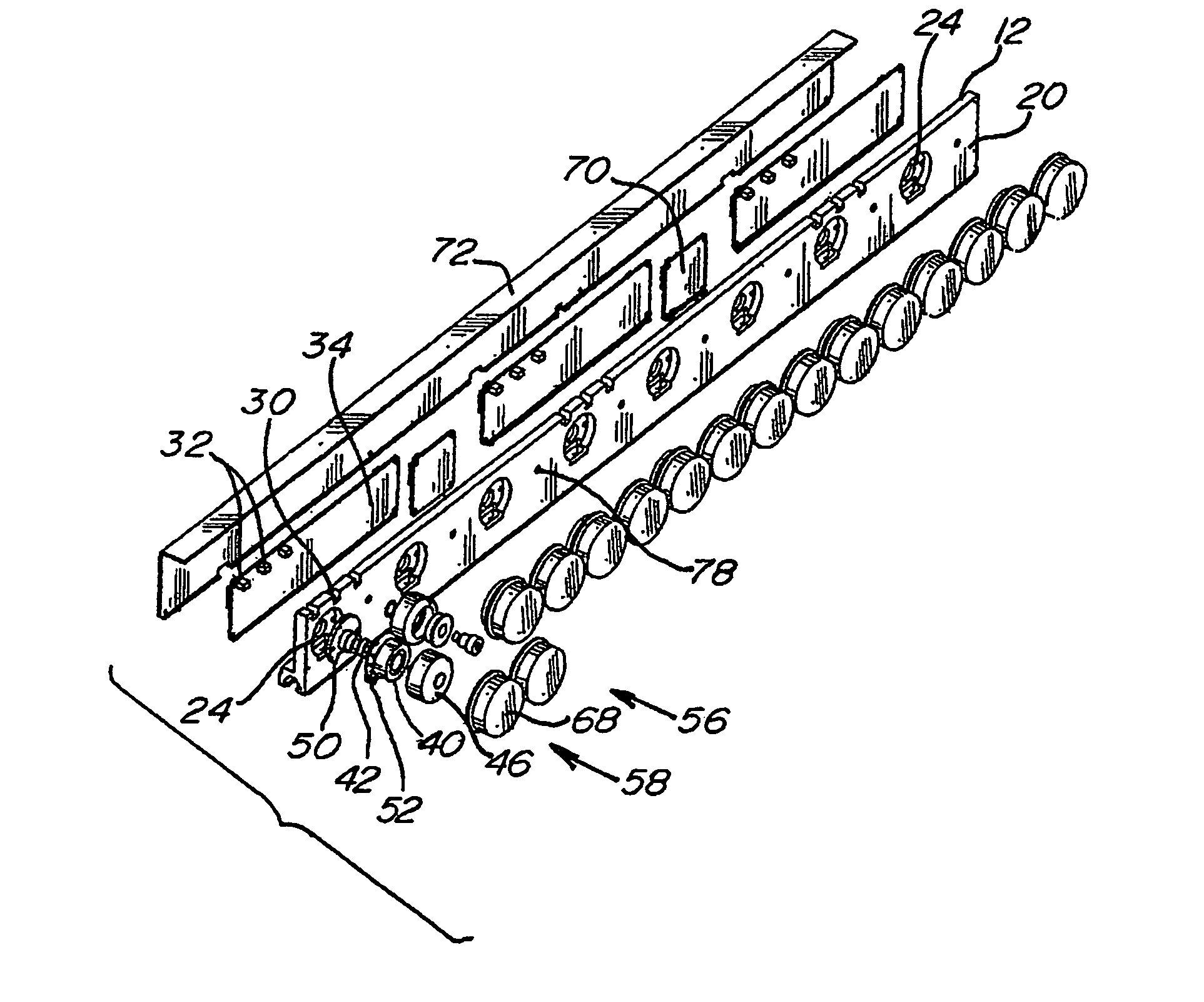
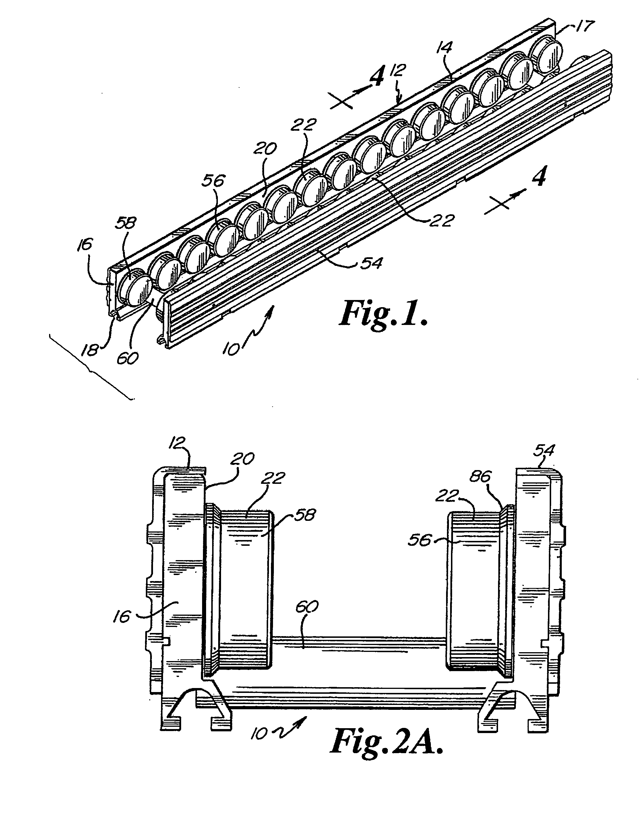
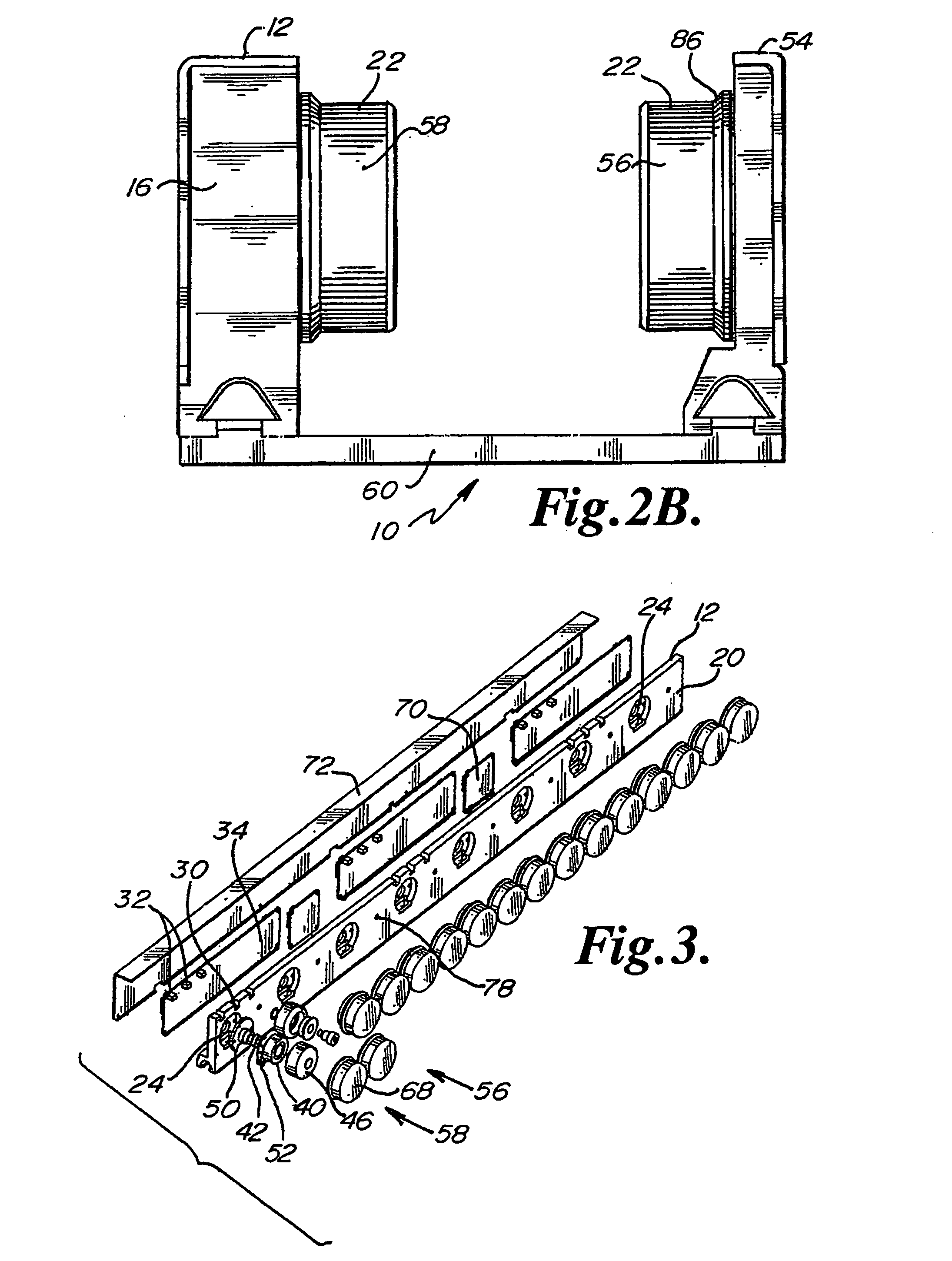
[0037] Referring to FIGS. 1-2B, an embodiment of a conveyor assembly 10 according to the present invention is depicted. The conveyor assembly 10 desirably includes a first rail 12, a second rail 54, spacing members 60 and a plurality of rollers 22. The first rail 12 is desirably a drive rail, and may generally include a top surface 14, a first end 16, a second end 17, a channel 18 and an operational face 20. A plurality of rollers 22 are spaced along the operational face 20. In one embodiment, every other roller 22 of the drive rail 12 ...


PUM


Abstract

The conveyor apparatus disclosed herein is generally formed of a first rail and a second rail, each rail having a plurality of rollers. A portion of the rollers are desirably drive rollers, receiving power from an integral motor assembly. The motor generally comprises a stator that is coupled to the rail and an outer roller assembly rotatably coupled to the rail. The roller assembly includes an outer circumferential magnetized portion positioned in surrounding engagement to the motor stator and functions both as the motor rotor and the conveying surface of the roller. Non-slip roller covering material may be attached to the exterior of the roller assembly. A circuit board having logic controls is preferably in communication with at least one sensor and the motor rotor to regulate rotation of the motor rotor during use of the conveyor.

Description

CROSS-REFERENCE TO RELATED APPLICATIONS [0001] This application claims the benefit of Provisional Patent Application No. 60 / 397,234 filed Jul. 19, 2002, the entire contents of which are incorporated herein by reference.BACKGROUND OF THE INVENTION [0002] In the past, conveyors have been formed of passive rollers, mechanically rotated rollers or a combination thereof. The most common types of mechanical drive apparatus utilized to rotate rollers of a conveyer include, but are not necessarily limited to, belt drives, chain drives, and / or shaft drive mechanisms. The use of these types of drive mechanisms generally require relatively large conveyors or structures. In addition, the known types of conveyors or drive mechanisms are difficult to keep clean, as the belts, chains, and / or shaft drive mechanisms frequently accumulate dirt and / or become soiled during use. [0003] The known conveyor systems generally are undesirable for use within a clean room environment. Frequently, clean room sp...

Claims


Application Information

Patent Timeline
Patent Type & Authority Applications(United States)
IPC IPC(8): B65G15/60B65G13/06B65G13/11B65G39/12
CPCB65G13/06B65G39/12B65G13/11
Inventor HELGERSON, DAVID E.KOENIG, BRIAN D.JENSEN, STEVEN A.FRESONKE, JOHNHALL, TIMOTHY J.
Owner ACTIVAR TECHN PRODS GROUP
Why Eureka
Try Eureka