Method for detecting a gaze direction of an eye

a technology of eye gaze and direction, applied in the field of eye gaze direction detection, can solve problems such as interference with incident laser radiation, and achieve the effects of low energy consumption, high level of user convenience, and high level of precision

Active Publication Date: 2021-12-02
TRUMPF PHOTONIC COMPONENTS GMBH
View PDF0 Cites 2 Cited by
  • Summary
  • Abstract
  • Description
  • Claims
  • Application Information

AI Technical Summary

Benefits of technology

[0014]Based on the detected optical path length as well as the eye velocity, the eye movement can then be detected. In particular, starting from a known eye position, the gaze direction can be tracked according to any movements of the eye. The method thus allows precise determination of the eye's gaze movements in a particularly simple and efficient manner. The specific method of detecting the gaze direction using laser feedback interferometry, especially using the Doppler effect, offers the advantage of particularly high temporal sampling rate, so that the eye movements may be tracked with particularly high temporal resolution. In addition, the method offers the advantage of using simple and inexpensive components and evaluation algorithms, which have low energy requirements. Especially no computationally intensive image data processing is required. In addition, it is advantageous that moving components, such as scanning devices, will not be required, thus providing particularly flexible and robust applicabilities.
[0029]Preferably, the smart glasses further comprise an input and / or output device which is configured to receive an input from the user and / or to output an output to the user. Preferably, the input and / or output device comprises a projection device configured to project an image, especially onto a retina of the users eye. Preferably, the input and / or output device and the eye tracking arrangement are coupled to each other, especially via the control device of the eye tracking arrangement, such that especially the input and / or output device can be controlled depending on the eye movements of the eye. This enables particularly user-friendly operation of the smart glasses, the specific type of gaze detection providing high level of precision and simultaneously particularly low energy consumption as well as low costs.

Problems solved by technology

This backscattering portion interferes with the incident laser radiation, i.e. with the laser radiation propagating toward the eye.

Method used


Image

  • Method for detecting a gaze direction of an eye
  • Method for detecting a gaze direction of an eye
  • Method for detecting a gaze direction of an eye

Examples


first embodiment

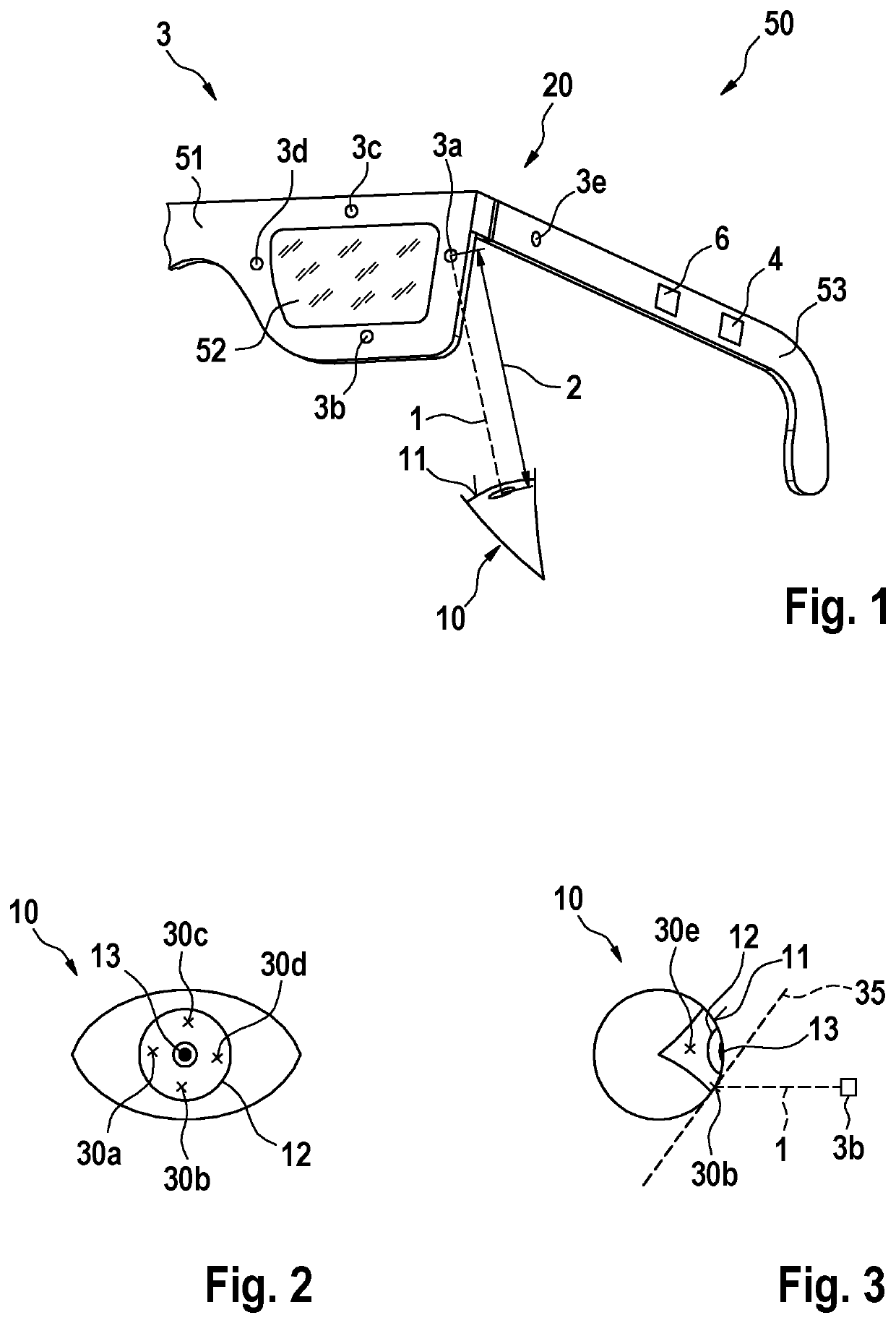
[0037]FIG. 1 shows a simplified schematic view of a pair of smart glasses 50 according to the invention. The smart glasses 50 comprise a spectacle lens 52, a spectacle frame 51 in which the spectacle lens 52 is received, and a spectacle temple 53 for holding the smart glasses 50 on a users head. The smart glasses 50 are thus configured to be worn on a users head.

[0038]The smart glasses 50 comprise a gaze detection arrangement 20, by which a gaze direction of an eye 10 of the user may be detected. For this purpose, the gaze detection arrangement 20 comprises a laser device 3 and a control device 4, which is configured to operate the laser device 4 to perform a respective method for detecting the gaze direction of the eye 10. The control device 4 is arranged in the spectacle temple 53 of the smart glasses 50 for compact design.

[0039]The laser device 3 includes a total of five surface emitters 3a, 3b, 3c, 3d, 3e as laser sources. Four of the five surface emitters 3a, 3b, 3c, 3d are dis...

second embodiment

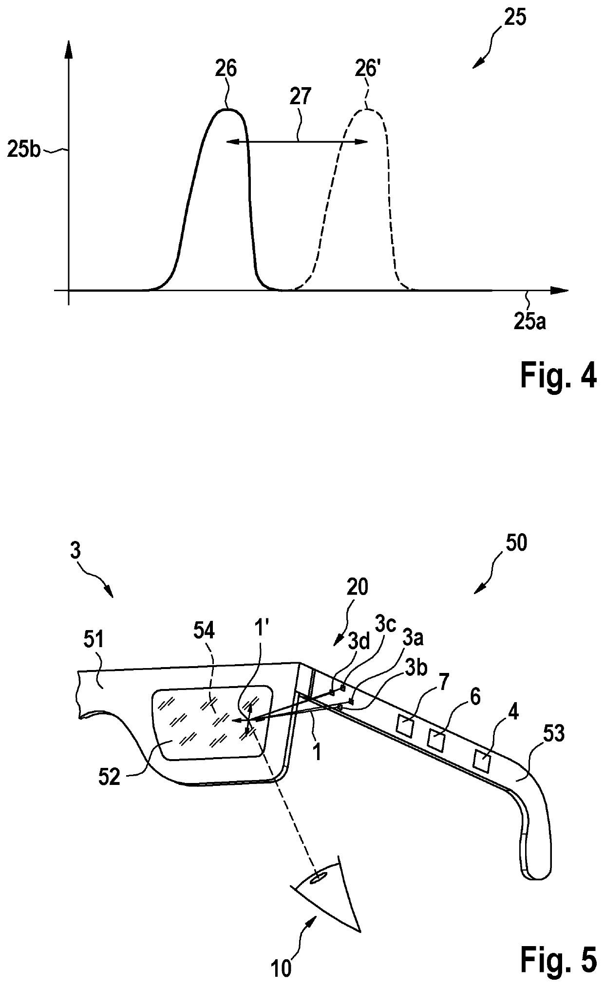
[0051]Furthermore, the smart glasses 50 of FIG. 5 additionally comprise an input and / or output device 7 which is configured to output an output to the user. The input and / or output device 7 comprises a projection unit, which is configured to project an image onto a retina of the eye 10. The projection unit can be used, for example, to display an augmented reality or virtual reality. Preferably, the projection unit is coupled to the control device 4, wherein the control device 4 is configured to operate the projection unit in response to the detected gaze direction. For example, the projected image can be adapted depending on the gaze direction.

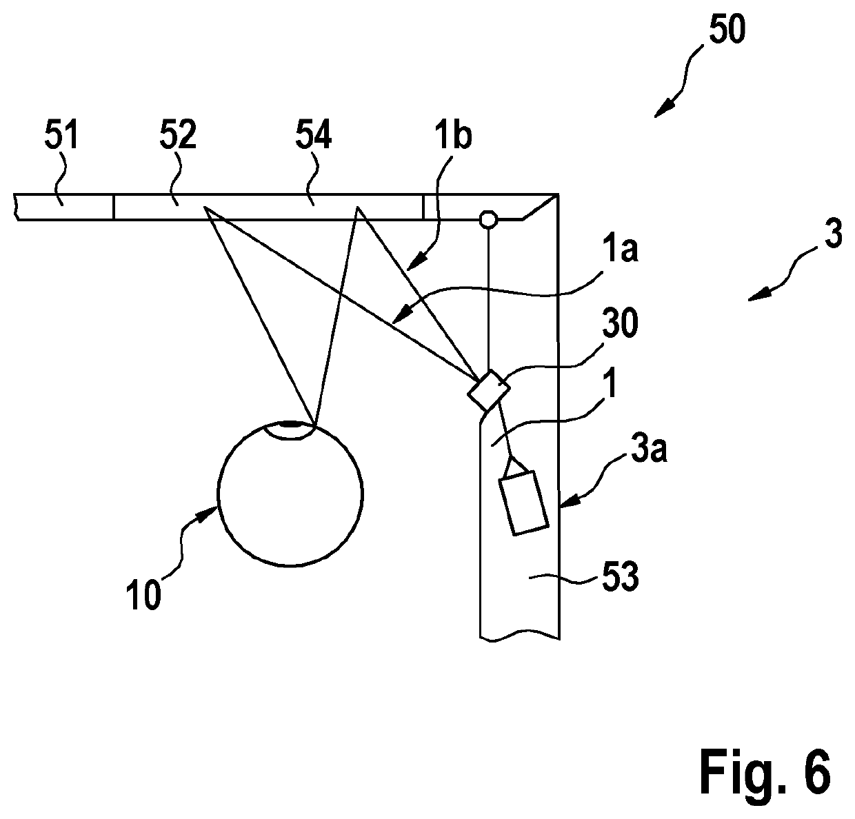
[0052]FIG. 6 shows a simplified schematic view of a pair of smart glasses 50 according to a third embodiment example of the invention. The third embodiment example essentially corresponds to the second embodiment example of FIG. 5 but having an alternative embodiment of the laser device 3.

[0053]In the third embodiment example, the laser device...


PUM


Abstract

A method for detecting a gaze direction of an eye includes the steps of irradiating at least one wavelength-modulated laser beam onto an eye, detecting an optical path length of the emitted laser beam based on laser feedback interferometry of the emitted laser radiation with a backscattered radiation from the eye, detecting a Doppler shift of the emitted radiation and the backscattered radiation based on the laser feedback interferometry, detecting an eye velocity based on the Doppler shift, and detecting an eye movement of the eye based on the optical path length and the eye velocity.

Description

PRIOR ART[0001]The present invention relates to a method for detecting a gaze direction of an eye and a gaze direction detection arrangement as well as a pair of smart glasses.[0002]The use of eye-tracking or eye detection (also known as oculography) to determine eye movements and to estimate a gaze direction is well known. Known systems for eye tracking are often based on detecting information on the eye position using camera-based systems, or using electrical or electromagnetic sensors in the region of the eye. In addition, scanned laser systems are known, which, for example, use micromirrors to scan a laser spot across the eye. All of these systems usually come with high complexity and energy consumption, mostly having limited temporal resolution.DISCLOSURE OF THE INVENTION[0003]Contrary to this, the method according to the invention having the features of claim 1 is characterized by a particularly energy-saving, cost-effective and temporally high-resolution approach to gaze dete...

Claims


Application Information

Patent Timeline
Patent Type & Authority Applications(United States)
IPC IPC(8): G02B27/00G02B27/01G02B27/10G01P3/36G01S17/58
CPCG02B27/0093G02B27/0172G02B27/0179G02B2027/0187G01P3/366G01S17/58G02B2027/0178G02B27/1006A61B3/113G01P3/36G01S17/34G01S17/88G01S17/66G01S7/4815G02B2027/0138G02B2027/014
Inventor PETERSEN, ANDREASSCHLEBUSCH, THOMAS ALEXANDERMEYER, JOHANNESSPRUIT, HANSHELLMIG, JOCHEN
Owner TRUMPF PHOTONIC COMPONENTS GMBH
Why Eureka
Try Eureka