Method for operating a pair of smart glasses

a technology for glasses and glasses, applied in the field of smart glasses, can solve problems such as interference with incident laser radiation, and achieve the effect of precise scanning of the ey

Active Publication Date: 2021-12-02
TRUMPF PHOTONIC COMPONENTS GMBH
View PDF0 Cites 2 Cited by
  • Summary
  • Abstract
  • Description
  • Claims
  • Application Information

AI Technical Summary

Benefits of technology

[0029]Preferably, the at least one surface emitter having a photodiode integrated therein is arranged on a spectacle frame and / or on a spectacle temple. In this context, a spectacle frame is especially regarded as a region of the smart glasses that surrounds the spectacle lens, and a spectacle temple is especially regarded as a holding temple that is connected to the spectacle frame, for example extending to an ear of the user. For example, several surface emitters having integrated photodiodes can distributedly be arranged around the spectacle lens on the spectacle frame, allowing particularly precise scanning of the eye over its entire range of motion. Alternatively or additionally, one or more laser sources may be integrated, preferably molded, into the spectacle lens.

Problems solved by technology

This backscattering portion interferes with the incident laser radiation, i.e. with the laser radiation propagating toward the eye.

Method used


Image

  • Method for operating a pair of smart glasses
  • Method for operating a pair of smart glasses
  • Method for operating a pair of smart glasses

Examples


Embodiment Construction

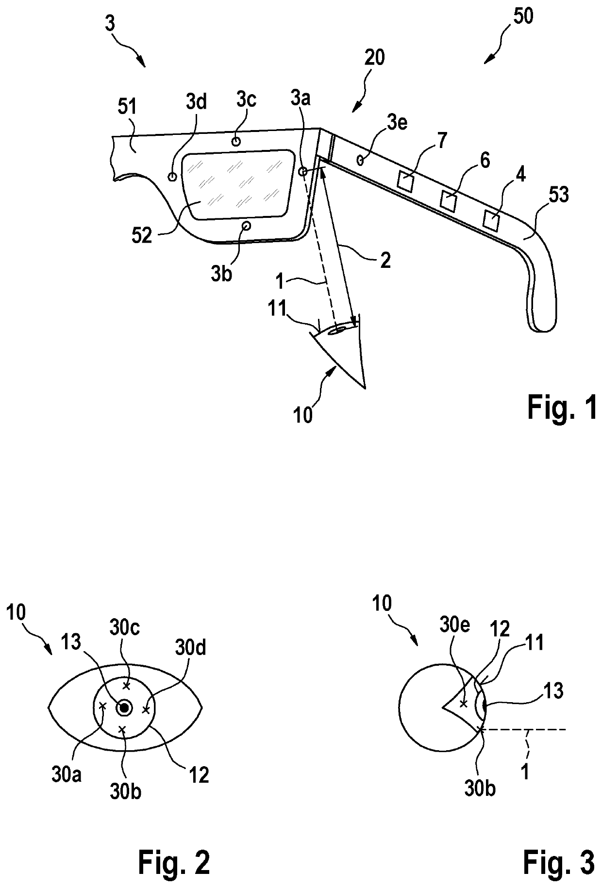
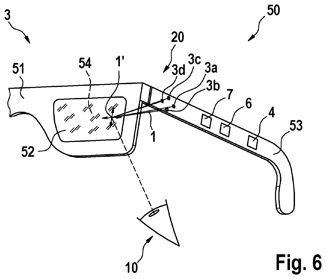
[0037]FIG. 1 shows a simplified schematic view of a pair of smart glasses 50 according to a first embodiment of the invention. The smart glasses 50 comprise a spectacle lens 52, a spectacle frame 51 in which the spectacle lens 52 is received, and a spectacle temple 53 for holding the smart glasses 50 on a users head. The smart glasses 50 are thus configured to be worn on a users head.

[0038]The smart glasses 50 comprise a gaze detection arrangement 20, by which a gaze direction of an eye 10 of the user may be determined. For this purpose, the gaze detection arrangement 20 comprises a laser device 3 and a control device 4, which is arranged to operate the laser device 4 to perform a corresponding method for detecting the gaze direction of the eye 10. The control device 4 is arranged in the temple 53 of the smart glasses 50 for compact design.

[0039]The laser device 3 includes a total of five surface emitters 3a, 3b, 3c, 3d, 3e as laser sources. Four of the five surface emitters 3a, 3b,...


PUM


Abstract

A method for operating smart glasses includes an input unit and/or output unit and a gaze detection arrangement, wherein the gaze detection arrangement detects any eye movement of an eye including the steps of irradiating at least one wavelength-modulated laser beam to the eye, detecting an optical path length of the emitted laser beam based on laser feedback interferometry of the emitted laser radiation with backscattered radiation from the eye, detecting a Doppler shift of the emitted and backscattered radiation based on the laser feedback interferometry, and detecting an eye velocity based on the Doppler shift, and wherein the input unit and/or output unit is operated based on the optical path length and/or the eye velocity.

Description

PRIOR ART[0001]The present invention relates to a method for operating smart glasses as well as smart glasses.[0002]The use of eye-tracking or eye detection (also known as oculography) to determine eye movements and to estimate a gaze direction is well known. The use of smart glasses is also known for the projection of images, for example onto a user retina. For example, gaze detection is used to adjust a control device of a projection unit of the pair of smart glasses, for example in displaying context-sensitive information. U.S. Pat. No. 7,637,615 B2 discloses such smart glasses using retina projection and eye tracking based on prism mirrors. Known systems for eye tracking are often based on detecting information on the eye position using camera-based systems or electrical or electromagnetic sensors in the region of the eye. In addition, scanned laser systems are known, which, for example, use micromirrors to scan a laser spot across the eye. All of these systems usually come with...

Claims


Application Information

Patent Timeline
Patent Type & Authority Applications(United States)
IPC IPC(8): G06F3/01
CPCG06F3/013G02C11/10G06F3/017G02B27/0093G02B27/0172G02B2027/0178G02B2027/0147G02B2027/0118
Inventor PETERSEN, ANDREASSCHLEBUSCH, THOMAS ALEXANDERMEYER, JOHANNESSPRUIT, HANSHELLMIG, JOCHEN
Owner TRUMPF PHOTONIC COMPONENTS GMBH
Why Eureka
Try Eureka