Scissor thrust valve actuator

a thrust valve and actuator technology, applied in the direction of valve operating means/releasing devices, service pipe systems, transportation and packaging, etc., can solve the problems of high torque dependence of many conventional valves, time-consuming and expensive testing, and often present operation and/or control problems in actuator designs

Inactive Publication Date: 2006-01-26
BATTELLE ENERGY ALLIANCE LLC
View PDF19 Cites 34 Cited by
  • Summary
  • Abstract
  • Description
  • Claims
  • Application Information

AI Technical Summary

Benefits of technology

[0006] A valve actuator according to one embodiment of the present invention may comprise a frame disposed in a substantially stationary, operative relationship with a valve, and first and second linkage arms. A first end of the first linkage arm is operatively connected to the frame. A second end of the second linkage arm is operatively connected to a valve stem of the valve. A screw block is operatively connected to the first and second linkage arms so that the second end of the first linkage arm is operatively connected to the screw block and the first end of the second linkage arm is also operatively connected to the screw block. A motor drive system includes a motor driven shaft that is in operative threaded screw driving relationship with the screw block so that when the motor driven shaft is rotated by a motor of the motor drive system, the motor driven shaft drives translational movement of the screw block which in turn drives the movement of the first and second linkage arms which in turn drives translational movement of the valve stem. A sensory control element operatively associated with the motor drive system and the valve senses a position of the valve and operates the motor drive system in accordance with a sensed position of the valve.

Problems solved by technology

Unfortunately, conventional valve actuator designs may often present operation and / or control problems.
Such testing is both time consuming and expensive.
Some of the problems of conventional motor-operated valves may be inherent in the respective designs thereof.
For example, many conventional valves are highly torque dependent.
However, many of the actual valves are of a type having a rising valve stem which requires a substantially linear thrust load.
But, when high seating and unseating forces are required, as in the case of large diaphragm, gate and / or globe valves, the currently available actuators are often exceedingly complex with highly-specialized motors being required to give the high torques necessary to provide the desired valve movement forces to open and / or close the valve.

Method used


Image

  • Scissor thrust valve actuator
  • Scissor thrust valve actuator
  • Scissor thrust valve actuator

Examples


Embodiment Construction

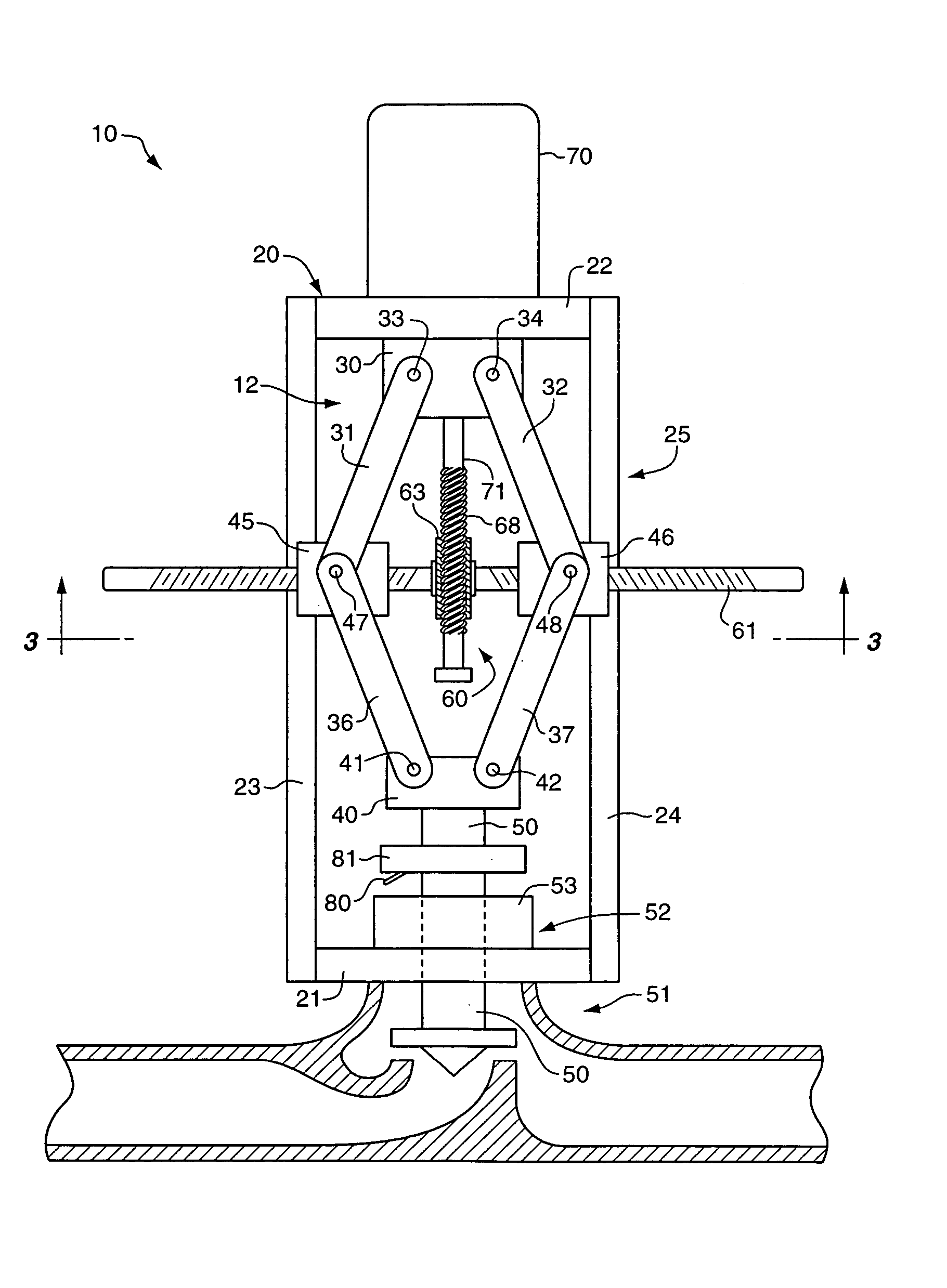
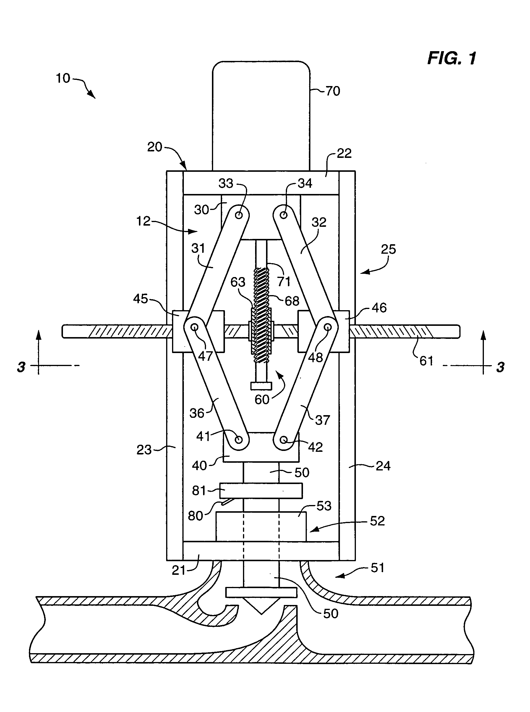
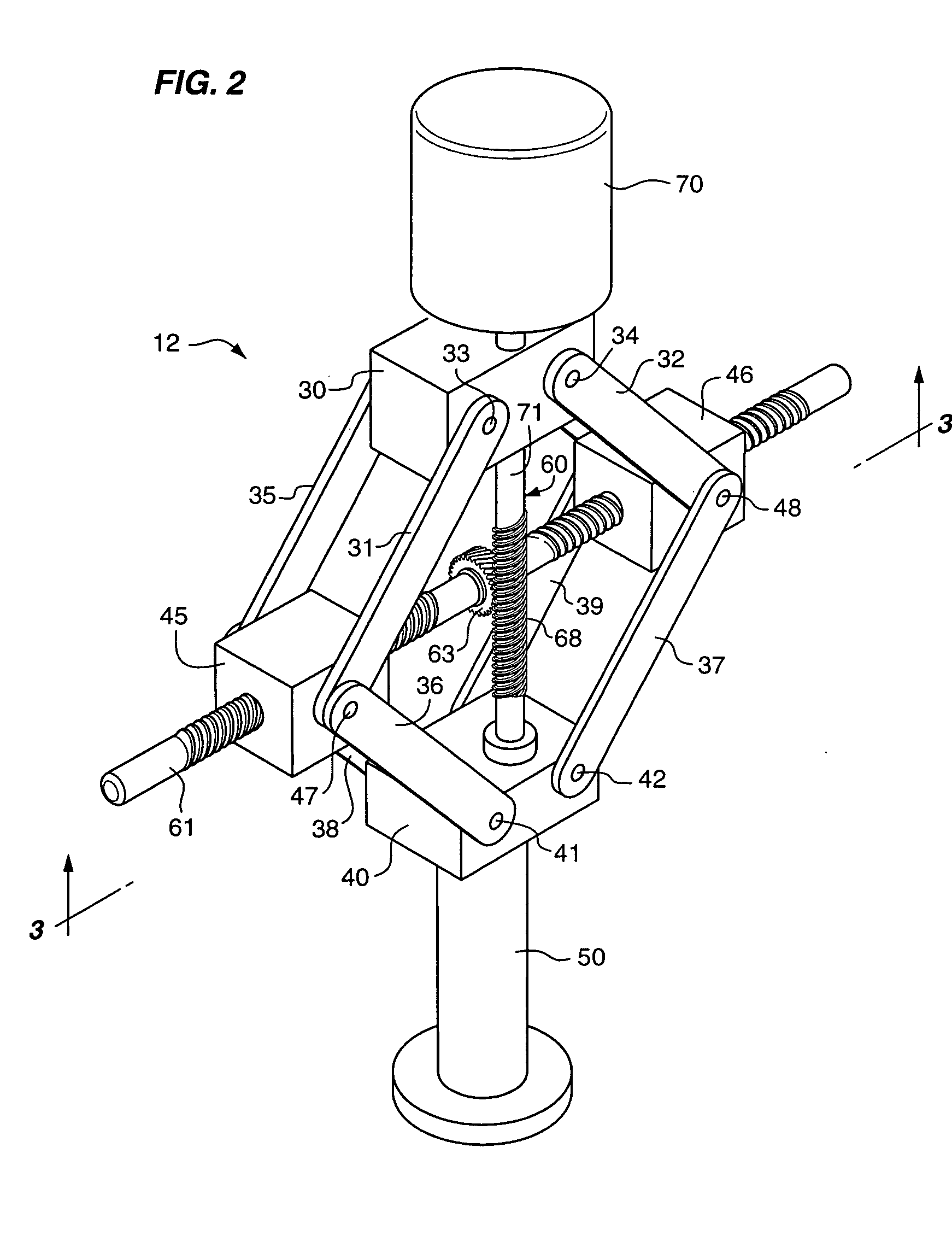
[0013] An exemplary valve actuator 10 according to the present invention will now be described with reference to the drawings. Starting with FIG. 1, an actuator 10 is shown which generally includes a mechanical drive mechanism 12 operably attached to a relatively stationary frame assembly 20. As will be described further, such a combination provides a valve actuator adapted to apply high, yet controlled mechanical forces with relatively low power input.

[0014] A frame assembly 20 of an actuator 10 may take many forms so long as it securely holds the other parts of the actuator 10 in proper operative, otherwise substantially movable relationship to a valve 51 to be actuated thereby. In some embodiments as shown in FIG. 1 for example, the frame 20 may be formed from and thus include a bottom mounting plate 21, top stationary or support plate 22, and elongated walls 23, 24 which may, in some embodiments, define a rectangular or a cylindrical enclosure identified generally by the refere...


PUM


Abstract

Apparatus for actuating a valve includes a support frame and at least one valve driving linkage arm, one end of which is rotatably connected to a valve stem of the valve and the other end of which is rotatably connected to a screw block. A motor connected to the frame is operatively connected to a motor driven shaft which is in threaded screw driving relationship with the screw block. The motor rotates the motor driven shaft which drives translational movement of the screw block which drives rotatable movement of the valve driving linkage arm which drives translational movement of the valve stem. The valve actuator may further include a sensory control element disposed in operative relationship with the valve stem, the sensory control element being adapted to provide control over the position of the valve stem by at least sensing the travel and/or position of the valve stem.

Description

CONTRACTUAL ORIGIN OF THE INVENTION [0001] This invention was made with United States Government support under Contract No. DE-AC07-99ID13727 awarded by the United States Department of Energy. The United States Government has certain rights in the invention.TECHNICAL FIELD [0002] This invention relates to valve actuator systems in general. BACKGROUND [0003] A commonly found safety-related component in government facilities, commercial nuclear power plants, and navy power plants is a motor operated or actuated valve. Such valves perform a wide range of safety related functions, from for example, containment isolation to controlling high-pressure coolant injection, as these are particularly well understood in the nuclear power area. Unfortunately, conventional valve actuator designs may often present operation and / or control problems. [0004] In nuclear power plant situations, U.S. and international regulators have responded to such operational and control problems by requiring frequen...

Claims


Application Information

Patent Timeline
Patent Type & Authority Applications(United States)
IPC IPC(8): F16K31/02
CPCF16K31/53F16K31/046F16K31/52F16K37/0041Y10T137/8242
Inventor DEWALL, KEVIN G.WATKINS, JOHN C.NITZEL, MICHAEL E.
Owner BATTELLE ENERGY ALLIANCE LLC
Why Eureka
Try Eureka