
Flexible tube for an exhaust pipe of an automobile

a flexible tube and automobile technology, applied in the direction of adjustable joints, mechanical devices, machines/engines, etc., can solve the problems of increased vibration of the exhaust pipe while driving, and increased vibration so as to reduce the generation of noise and harshness caused by over-vibration of the exhaust system, improve the endurance of the flexible tube, and improve the effect of the evaluation of the automobil

Inactive Publication Date: 2006-01-26
SJM
View PDF43 Cites 8 Cited by
  • Summary
  • Abstract
  • Description
  • Claims
  • Application Information

AI Technical Summary

Benefits of technology

[0011] The object of the present invention is to provide a flexible tube for an exhaust pipe of an automobile, which includes a spring member along a circumferential surface of outer braids thereof, so that the vibration of the flexible tube and the generation of noise and harshness caused by over-vibration of an exhaust system can be suppressed and the N.V.H. evaluation of the automobile and the endurance of the flexible tube can be improved.

Problems solved by technology

These days, automobiles tend to have an increased vibration of engine roll in case of engine starting, abrupt starting and braking of an automobile or gear shifting, due to increased output of power from the engine.
Further, depending on various conditions of roads, the vibration of an exhaust pipe is generated while driving.
Accordingly, when over-vibration occurred in the exhaust system, the vibration on the flexible tube increased, in which case the outer braids (30) enclosing the bellows member (10) came into contact with the bellows member (10) intermittently and such contact caused abrasion and noise.
Thus, N.V.H. (noise, vibration & harshness) evaluation deteriorated and the endurance of the flexible tube became reduced.

Method used


Image

  • Flexible tube for an exhaust pipe of an automobile
  • Flexible tube for an exhaust pipe of an automobile
  • Flexible tube for an exhaust pipe of an automobile

Examples


Embodiment Construction

[0024] Reference will now be made in detail to preferred embodiments of the present invention in conjunction with the accompanying drawings.

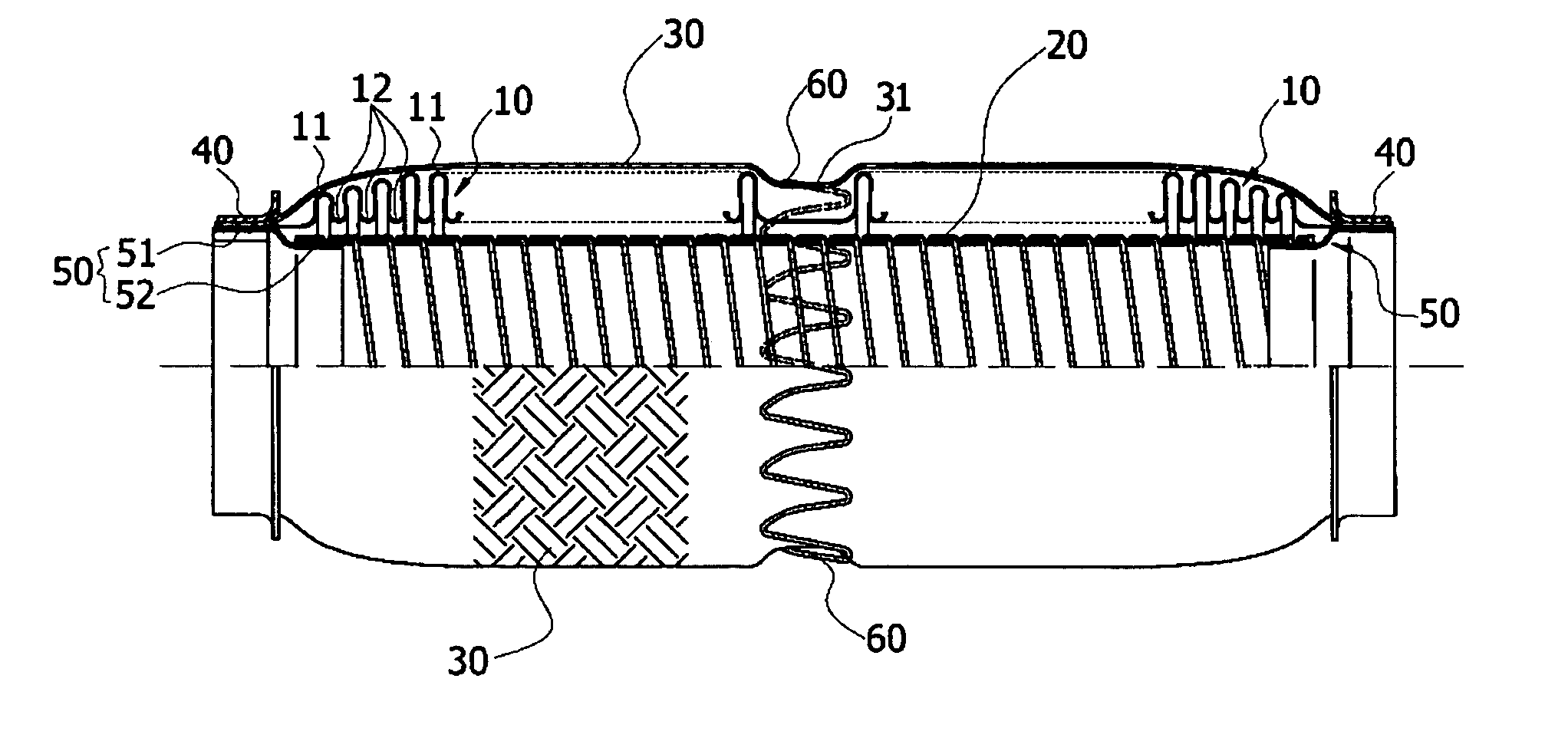
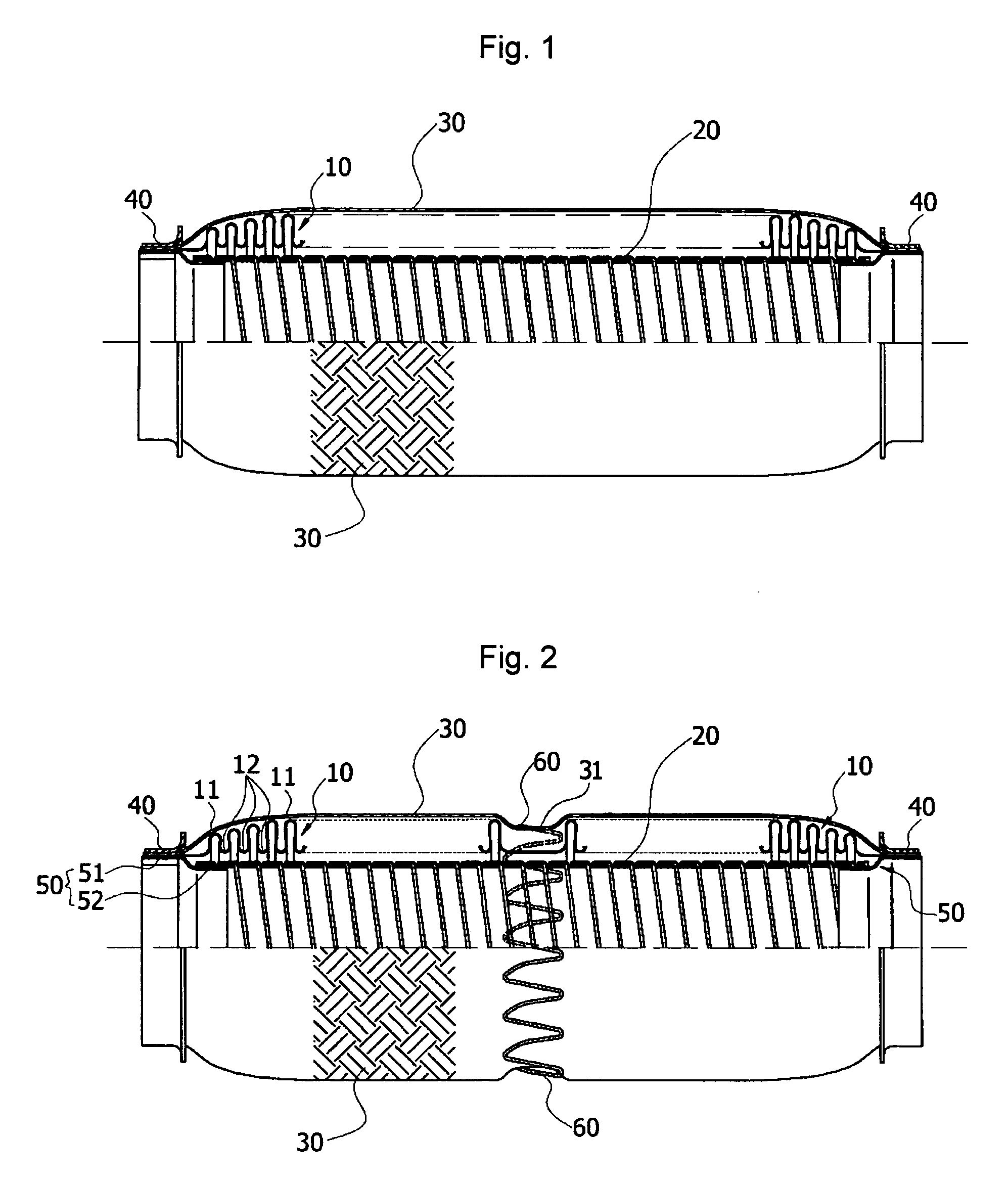
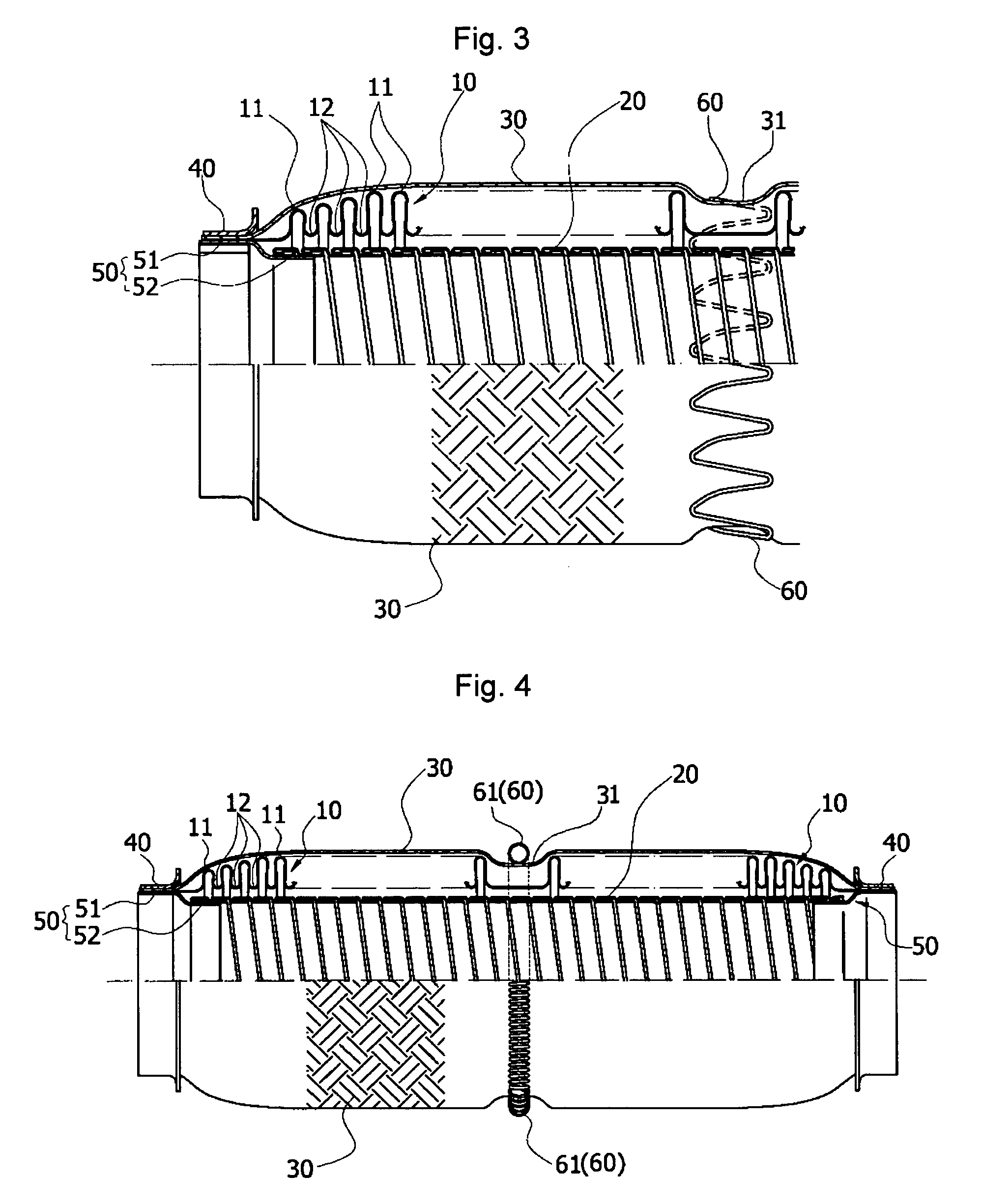
[0025]FIG. 2 shows the basic structure of a flexible tube for an exhaust pipe of an automobile according to the present invention and FIG. 3 shows a partially enlarged view of FIG. 2, wherein a groove (31) for mounting a spring member (60) thereon is formed along the central circumferential surface of outer braids (30) and the spring member (60) is seated on the groove (31) to closely contact the central circumferential surface of the outer braids (30).

[0026]FIG. 4 shows another embodiment of the flexible tube for an exhaust pipe of an automobile according to the present invention and FIG. 5 shows a partially enlarged view of FIG. 4, wherein a coil spring (61) is mounted on the groove (31) in place of the spring member (60).

[0027] Referring to FIGS. 2 and 3, the flexible tube of the present invention comprises a bellows member (10), and the b...


PUM


Abstract

A flexible tube for an exhaust pipe of an automobile, which has a spring member provided along a circumferential surface of outer braids thereof, so that the vibration of the flexible tube and the generation of noise and harshness caused by over-vibration of an exhaust system can be suppressed and riding comfort of drivers and passengers can be improved. The flexible tube according to the present invention comprises a bellows member (10) corrugated to have alternate ridges (11) and furrows (12) along its outer periphery; outer braids (30) provided at a predetermined distance from the outer periphery of the bellows member (10); fixing caps (40) fitted onto both side ends of the outer braids (30) respectively; and a spring member (60) provided on a circumferential surface of the outer braids (30) to be closely contacted thereto.

Description

FIELD OF THE INVENTION [0001] The present invention relates to a flexible tube for an exhaust pipe of an automobile, and more particularly to a flexible tube having a spring member provided along a circumferential surface of outer braids thereof, so that the vibration of the flexible tube and the generation of noise and harshness caused by over-vibration of an exhaust system can be suppressed and riding comfort of drivers and passengers can be improved. BACKGROUND OF THE INVENTION [0002] These days, automobiles tend to have an increased vibration of engine roll in case of engine starting, abrupt starting and braking of an automobile or gear shifting, due to increased output of power from the engine. [0003] Further, depending on various conditions of roads, the vibration of an exhaust pipe is generated while driving. [0004] Therefore, an engine of an automobile is connected to the exhaust pipe so that the exhaust gas can be discharged, and in an intermediate part between the engine a...

Claims


Application Information

Patent Timeline
Patent Type & Authority Applications(United States)
IPC IPC(8): F16L27/12F01N13/08F01NF01N13/06F01N13/18F16L27/111F16L51/02
CPCF01N13/1816F16L51/027F16L27/111F01N2470/12F16L11/15F01N13/08F01N13/06
Inventor KIM
Owner SJM
Learn More