
Arrangement with an electric motor

Inactive Publication Date: 2006-01-26
EBM PAPST ST GEORGEN & -
View PDF5 Cites 88 Cited by
  • Summary
  • Abstract
  • Description
  • Claims
  • Application Information

AI Technical Summary

Benefits of technology

[0008] Such an arrangement makes possible “blind” installation, i.e. such a motor can simply be pushed into the cutout of the associated apparatus, the snap-lock element then snap-locking the motor therein. The snap-locking element is located in the same protected housing or cavity as the motor, so that the snap-locking element, like the motor, is protected from contamination and corrosion and can easily be detached again, if necessary, for example to swap out any failing component.

Problems solved by technology

Because of their relatively low outputs, such motors are sensitive to contamination, such as can often occur, for example, in a washing machine; an effort is therefore made to arrange such motors in a sealed space so that no dirt can reach them.
This requires, however, the creation of threaded holes or the setting of threaded rivets for bolt-on mounting, which is sometimes undesirable because such holes can result in weakening, and after a while can result in permanent breakage.

Method used


Image

  • Arrangement with an electric motor
  • Arrangement with an electric motor
  • Arrangement with an electric motor

Examples


Embodiment Construction

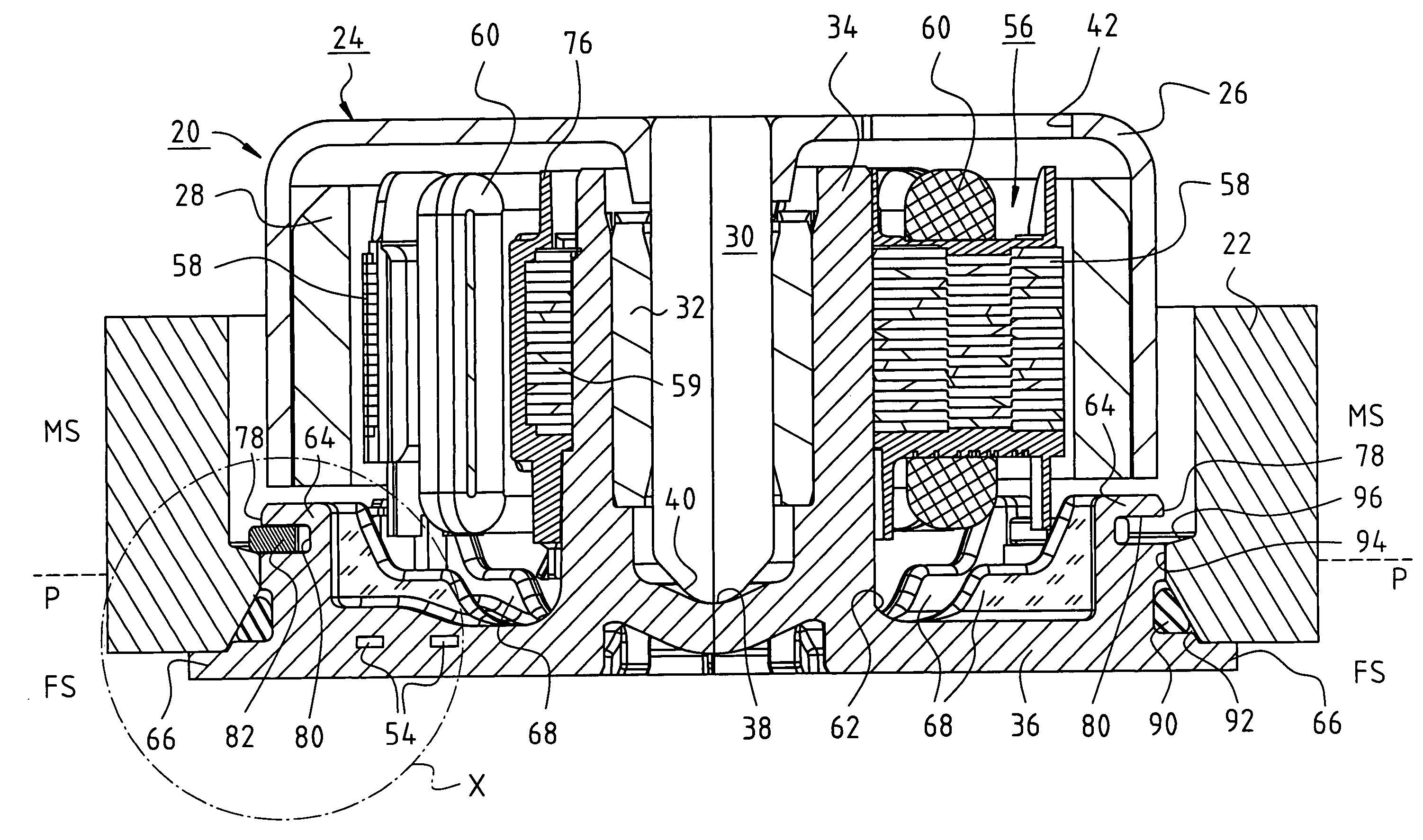
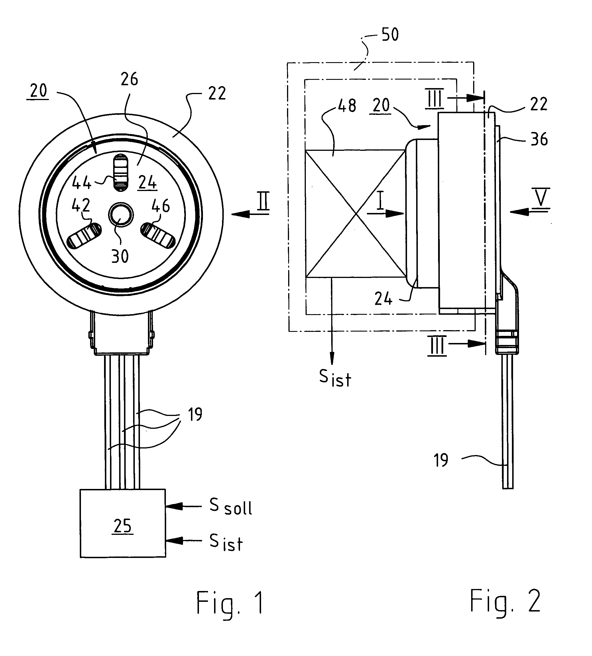
[0023]FIGS. 1 and 2 show, at approximately 1:1 scale, an external-rotor miniature motor 20 that is mounted in a generally annular mount or ring 22 which symbolizes an arbitrary apparatus, such as a wall or part of a housing. In this example, motor 20 is a three-phase motor in a star or delta configuration that is supplied for drive purposes, via three lines 19, with a three-phase current from, for example, an electronic position controller 25, to which a target value Ssoll for a desired position, and an actual value Sist for a current position, are delivered.

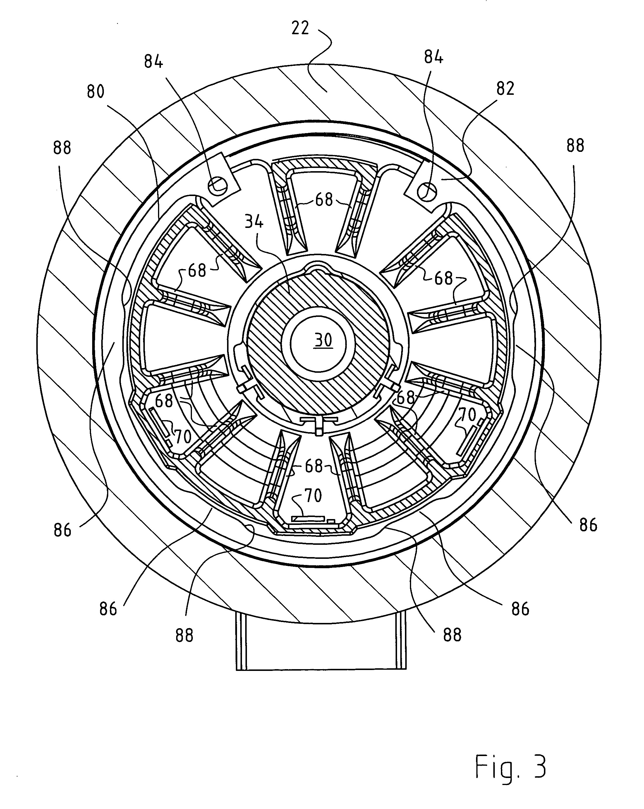
[0024] Motor 20 has an external rotor 24 having a so-called rotor cup 26 (FIG. 7) made of copper, in which is mounted a magnet ring 28 that is magnetized with, for example, four poles. Such motors are manufactured by the assignee of this application, and are known.

[0025] As FIG. 7 shows, there is mounted, on rotor cup 26, a shaft 30 that is supported in a plain bearing 32, which in turn is mounted in a bearing tube 34, by bein...


PUM


Abstract

An arrangement with an electric motor facilitates mounting of the motor, particularly of a miniature or subminiature motor. The motor (20) has a stator (56), a rotor (24), and a support flange (36) coupled to the motor. A motor mount (22) is formed with an opening (94) for engagement with the support flange (36). The opening has, on its rim, a motor-side shoulder (96) that has a substantially frustoconical shape and faces axially toward the motor (20) after mounting. The support flange (36) is shaped for guidance of a snap-lock element (82) that extends along at least a portion of the circumference of the support flange (36) and is resiliently deflectable radially inward, by means of an inwardly directed force. The snap-lock element (82) is so configured that it snap-locks outward against the motor-side shoulder (96) of the opening (94) when the motor is mounted.

Description

CROSS-REFERENCE [0001] This application claims priority from German application DE 10 2004 036 887.2, filed 21 Jul. 2004, the contents of which are incorporated by reference. FIELD OF THE INVENTION [0002] The present invention relates generally to an arrangement with an electric motor, and in particular to a mounting arrangement for a so-called miniature or subminiature motor. BACKGROUND [0003] Miniature motors of this kind are used for a variety of tasks, for example to drive miniature or subminiature fans; to drive pumps, for example in medical devices; as actuating motors, etc. Such a motor can have a weight, for example, in the range from approximately 50 grams to approximately 250 grams. [0004] Because of their relatively low outputs, such motors are sensitive to contamination, such as can often occur, for example, in a washing machine; an effort is therefore made to arrange such motors in a sealed space so that no dirt can reach them. This applies in particular to motors that ...

Claims


Application Information

Patent Timeline
IPC IPC(8): H02K11/00G11B17/08H02K5/00
CPCH02K5/00H02K21/22H02K5/225H02K5/1735
Inventor HAHN, ALEXANDERNICKEL-JETTER, MATTHIAS
Owner EBM PAPST ST GEORGEN & -
Features
  • Generate Ideas
  • Intellectual Property
  • Life Sciences
  • Materials
  • Tech Scout
  • Unparalleled Data Quality
  • Higher Quality Content
  • 60% Fewer Hallucinations
Learn More