Sliding assisting apparatus

Inactive Publication Date: 2006-01-26
NIFCO INC
View PDF11 Cites 28 Cited by
  • Summary
  • Abstract
  • Description
  • Claims
  • Application Information

AI Technical Summary

Benefits of technology

[0019] With the drawing-out/drawing-in unit main body and the strikers, it is possible to slide respectively to the final drawn-out position and the final drawn-in position automatically by the force of the urging device, in the process of switching the movable body from the drawn-in position to the drawn-out position, and in the process of switching the movable body from the drawn-out position to the drawn-in position, that is, from each mid-course position, thereby improving convenience. Because both assisting functions of drawing in and drawing out can be achieved by the single unit construction, it becomes advantageous in such points as that it has excellent building-in characteristics and maintenance characteristics, and it tends not to be limited in setup space.
[0020] Because the front end sides of the respective lock members are made to protrude out toward the same direction from the long groove on the case in a state in which the respective sliders hold the lock members in the holding parts, compactness is devised, and a deg

Problems solved by technology

In a structure in which a movable body is switched to slide between a drawn-in position and a drawn-out position on a main body, as disclosed in Patent Document 1, it is tiresome and lacks a feeling of high quality as all of the switching operations are performed by a hand.
In the above-mentioned conventional structure, for example, although the movable body is slid automatically almost entirely from the drawn-out position to the drawn-in position, a strong pulling operation force by that amount becomes necessary when going from the drawn-in position to the drawn-out position, and the convenience of use becomes poor.
Moreover, in the conventional structure, once the movable body is removed from the m

Method used


Image

  • Sliding assisting apparatus
  • Sliding assisting apparatus
  • Sliding assisting apparatus

Examples


Embodiment Construction

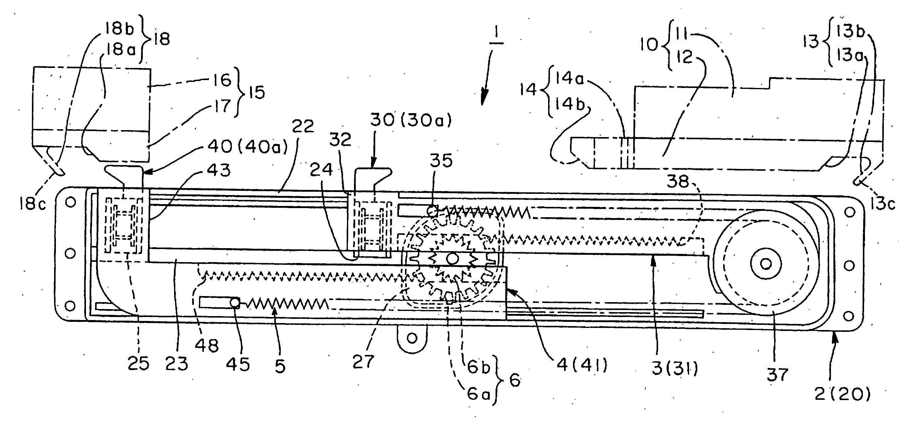
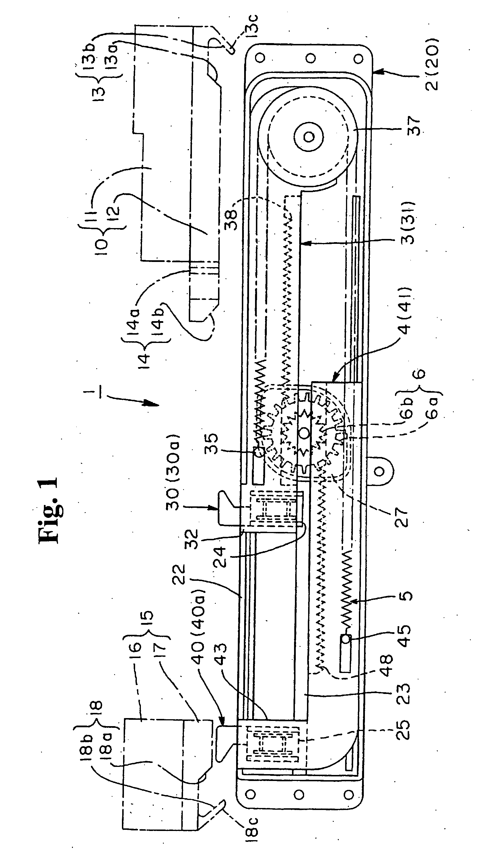
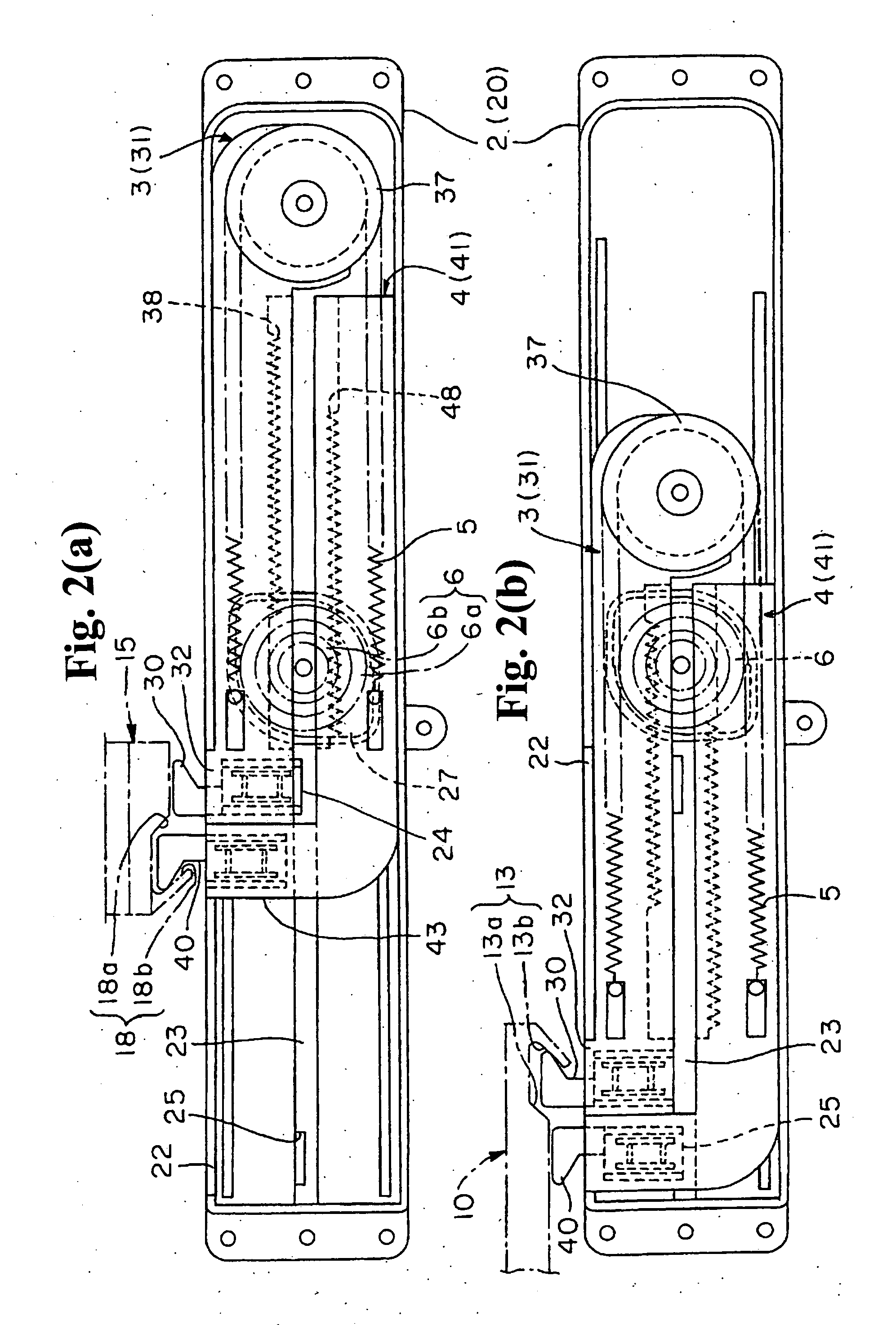
[0038] Hereunder, embodiments of the present invention will be explained with reference to the drawings. FIG. 1 and FIGS. 2(a) and 2(b) typically show the operation of the apparatus of the embodiment of the present invention. FIG. 1 is the state in which force is accumulated. FIGS. 2(a) and 2(b) are showing the state in which the force is released. FIG. 3 is structural drawings showing the relationships among the main components constituting said apparatus. FIGS. 4(a) and 4(b) are a top view and a side view showing the case main body of the apparatus together with the damper. FIG. 5 is a top view showing the cover attached to said case main body.

[0039] FIGS. 6(a) to 6(c) are one of the sliders constituting said apparatus; wherein FIG. 6(a) is a top view showing it together with the lock member, FIG. 6(b) is a side view, and FIG. 6(c) is a bottom view. FIGS. 7(a) to 7(c) are views showing the other slider; wherein FIG. 7(a) is a top view, FIG. 7(b) is a side view, and FIG. 7(c) is a...


PUM


Abstract

A sliding assisting apparatus assists a movable body to move between a drawn-out position and a drawn-in position. The apparatus includes a unit main body to be attached to a main body or the movable body, and a pair of strikers to be attached to the main body or movable body. The unit main body includes a pair of sliders slidably disposed inside a case, lock members movably supported on the respective sliders, coupling parts provided on the case for engaging the lock members, and an urging device provided between the sliders for accumulating a force when the sliders slide away from the other. One striker switches one slider between a case restrained position in which one coupling part engages one lock member and a case restraint released position in which the one coupling part releases the one lock member.

Description

BACKGROUND OF THE INVENTION AND RELATED ART STATEMENT [0001] The present invention relates to a sliding assisting apparatus for assisting an operation of a movable body such as a drawer or cover body to slide on a main body and switch between a drawn-in position and a drawn-out position. [0002] In a structure in which a movable body is switched to slide between a drawn-in position and a drawn-out position on a main body, as disclosed in Patent Document 1, it is tiresome and lacks a feeling of high quality as all of the switching operations are performed by a hand. Accordingly, it is dealt with in a manner such that the movable body is forced in either direction of the drawn-out position or the drawn-in position and is slid automatically toward the forced direction. [0003] FIGS. 14(a) and 14(b) show a drawer apparatus disclosed in Patent Document 1; wherein FIG. 14(a) is a state drawing of the drawn-in position of the movable body not illustrated, and FIG. 14(b) is the drawn-out posi...

Claims


Application Information

Patent Timeline
IPC IPC(8): A47B88/00A47B88/04E05F1/08E05F5/00
CPCA47B88/047A47B88/0477E05F1/16E05Y2800/24E05Y2800/00E05Y2900/20A47B88/0481E05F5/003A47B88/463A47B88/467A47B88/47A47B88/40E05F3/16E05F3/22E05F5/02E05F5/06
Inventor SATO, HIROJIKOBAYASHI, YASUTOMO
Owner NIFCO INC
Why Eureka
Try Eureka