Microscope imaging apparatus and biological-specimen examination system

a microscope and imaging apparatus technology, applied in the direction of instruments, measurement devices, scientific instruments, etc., can solve the problem of taking a long time to examine the entire micropla

Inactive Publication Date: 2006-01-26
OLYMPUS CORP
View PDF9 Cites 34 Cited by
  • Summary
  • Abstract
  • Description
  • Claims
  • Application Information

AI Technical Summary

Problems solved by technology

Since the fluorescence intensity of a biological specimen is extremely dark, it is necessary to capture the fluorescence using a long exposure time.
Also, since the microplate has a shape that is larger than the field of view of a microscope, it takes some time to examine the entire microplate.

Method used


Image

  • Microscope imaging apparatus and biological-specimen examination system
  • Microscope imaging apparatus and biological-specimen examination system
  • Microscope imaging apparatus and biological-specimen examination system

Examples


first embodiment

[0124] Next, a first embodiment of the present invention will be described. Here, a measurement procedure will be described using FIG. 7.

[0125]FIG. 7 is a flowchart showing the measurement procedure in this embodiment. FIGS. 8A to 8C show the relationship between the brightness of the specimen 20 and the output level from the imaging device 63. FIG. 8A shows the relationship between the brightness obtained in a first scan and the output level, FIG. 8B shows the relationship between the brightness obtained in a second scan and the output level, and FIG. 8C shows the dependency of the brightness obtained in the first and second scans no the output level.

[0126] First, the first scan (image acquisition) is performed to acquire an image of the specimen 20 (step S1). This corresponds to the prescan.

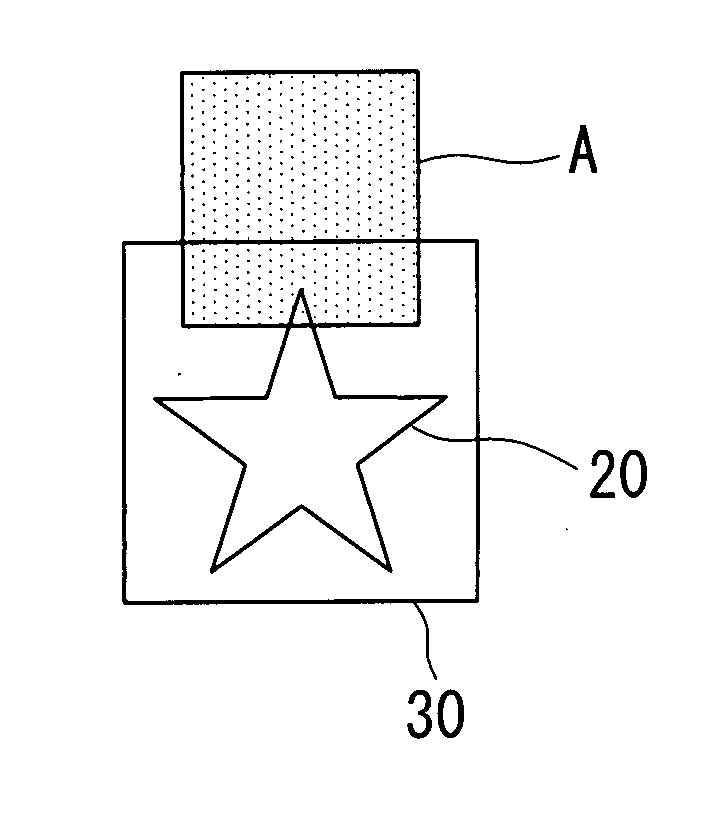
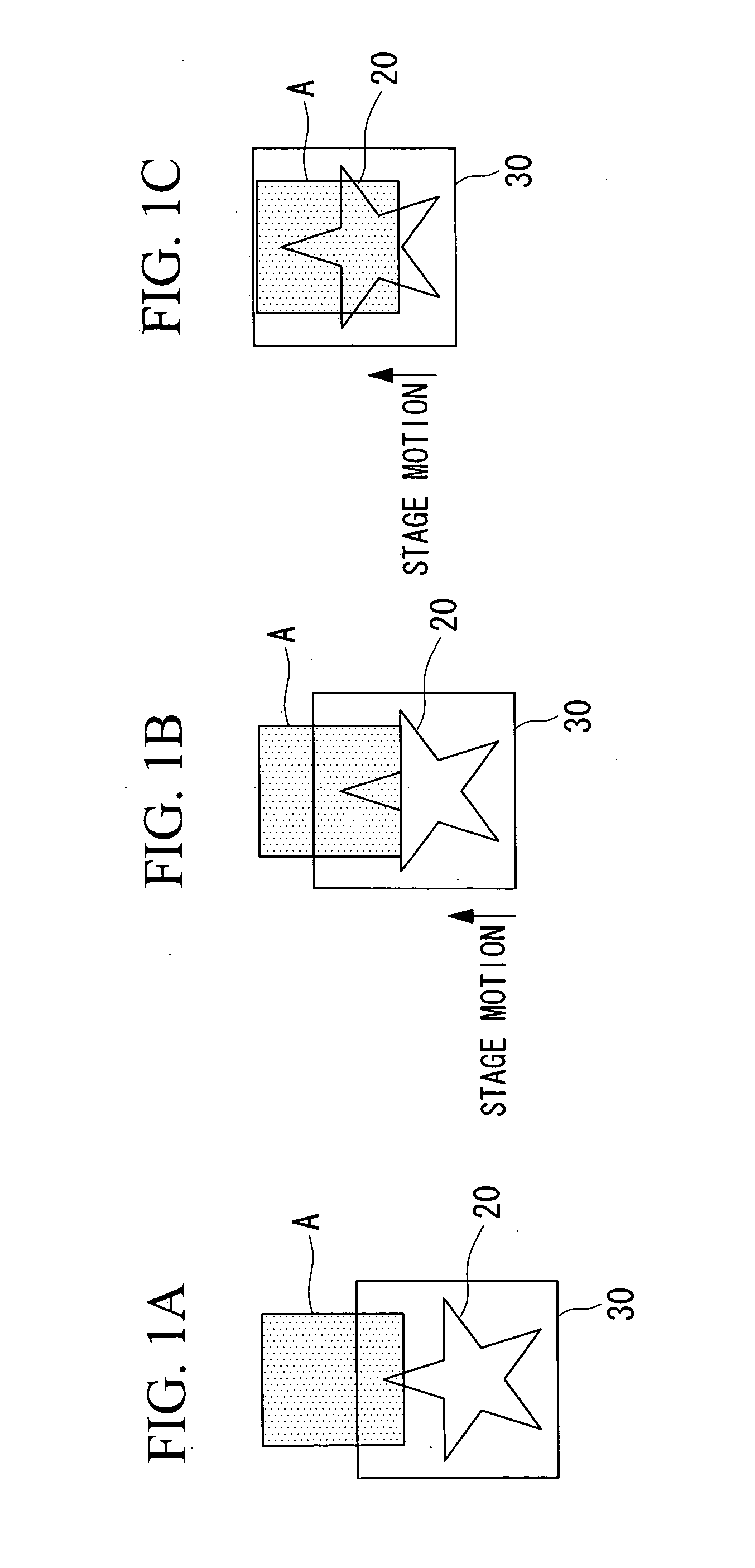
[0127] In this step, while the specimen 20 (stage 30) is moved from position a to position b shown in FIG. 6, the specimen 20 is imaged with a predetermined exposure time.

[0128] The image a...

second embodiment

[0154] Next, a second embodiment of the present invention will be described with reference to FIGS. 11 to 13.

[0155] The basic structure of the microscope imaging apparatus of this embodiment is the same as that of the first embodiment, but the method of measuring the specimen is different from that in the first embodiment. Therefore, in this embodiment, only the method of measuring the specimen shall be described, using FIGS. 11 to 13, and a description of the TDI method and so on shall be omitted.

[0156]FIG. 11 depicts the overall configuration of a microscope imaging apparatus 110 of this embodiment.

[0157] As shown in FIG. 11, the microscope imaging apparatus 110 includes a stage 30, an illumination unit 40, and an image-acquisition unit 160. The stage 30 holds a specimen 20 and is moveable. The illumination unit 40 irradiates the specimen 20 with illumination light. The image-acquisition unit 160 acquires signal light emitted from the region irradiated with illumination and mea...

third embodiment

[0174] Next, a third embodiment will be described with reference to FIGS. 14 and 15.

[0175] The basic configuration of the microscope imaging apparatus of this embodiment is the same as that in the first embodiment, but the configuration of the image-acquisition unit is different from the first embodiment. Therefore, in this embodiment only the image-acquisition unit will be described using FIGS. 14 and 15, and a description of the illumination unit and so on shall be omitted.

[0176]FIG. 14 shows the overall configuration of a microscope imaging apparatus 210 in this embodiment.

[0177] As shown in FIG. 14, the microscope imaging apparatus 210 includes a stage 30, an illumination unit 40, and an image-acquisition unit 260. The stage 30 holds a specimen 20 and is moveable. The illumination unit 40 irradiates the specimen 20 with illumination light. The image-acquisition unit 260 acquires signal light emitted from the region irradiated with the illumination light and measures it.

[0178...


PUM


Abstract

A microscope imaging apparatus and a biological-specimen examination system that can accurately carry out measurement even for an object under examination having substantial brightness non-uniformity are provided. The microscope imaging apparatus includes a stage that holds the object under examination, an illumination unit that illuminates the object under examination, an image-acquisition unit that acquires images of the object under examination, and a motion unit that moves the stage and the image-acquisition unit relative to each other. The image-acquisition unit includes an imaging device capable of image acquisition using a time delay integration method. When acquiring a plurality of images of the object under examination, the exposure time during which accumulated charge is produced in the imaging device is made different for each of the acquired images, and the plurality of images are combined into a single image.

Description

BACKGROUND OF THE INVENTION [0001] 1. Field of the Invention [0002] The present invention relates to a microscope imaging apparatus and to a biological-specimen examination system using the same. [0003] 2. Description of Related Art [0004] A known apparatus for measuring fluorescence and so on of a biological specimen uses a microplate. Since the fluorescence intensity of a biological specimen is extremely dark, it is necessary to capture the fluorescence using a long exposure time. Also, since the microplate has a shape that is larger than the field of view of a microscope, it takes some time to examine the entire microplate.[0005] One method of imaging such fluorescence is a method in which measurement is carried out with a CCD (charge coupled device) while the microplate is repeatedly moved and stopped. A plurality of wells are provided in the microplate, and the specimens are held in these wells. Therefore, by repeatedly moving and stopping the microplate, the fluorescence from ...

Claims


Application Information

Patent Timeline
Patent Type & Authority Applications(United States)
IPC IPC(8): G02B21/00
CPCG01N21/6452G01N21/6458G02B21/367G02B21/002G01N21/6486
Inventor SUZUKI, YOSHIMASAMURAKI, KAYURI
Owner OLYMPUS CORP
Why Eureka
Try Eureka