
Kd systems with robust timing

a timing system and key distribution technology, applied in the field ofquantum cryptography, can solve the problems of not being able to operate in the variety of operational modes not being able to maintain timing synchronization and control jitter in the timing signal, and not being able to program the system as designed to operate in the field. the variety of operational modes is needed in the field, and the system is not programmabl

Inactive Publication Date: 2006-01-26
MAGIQ TECH INC
View PDF18 Cites 52 Cited by
  • Summary
  • Abstract
  • Description
  • Claims
  • Application Information

AI Technical Summary

Benefits of technology

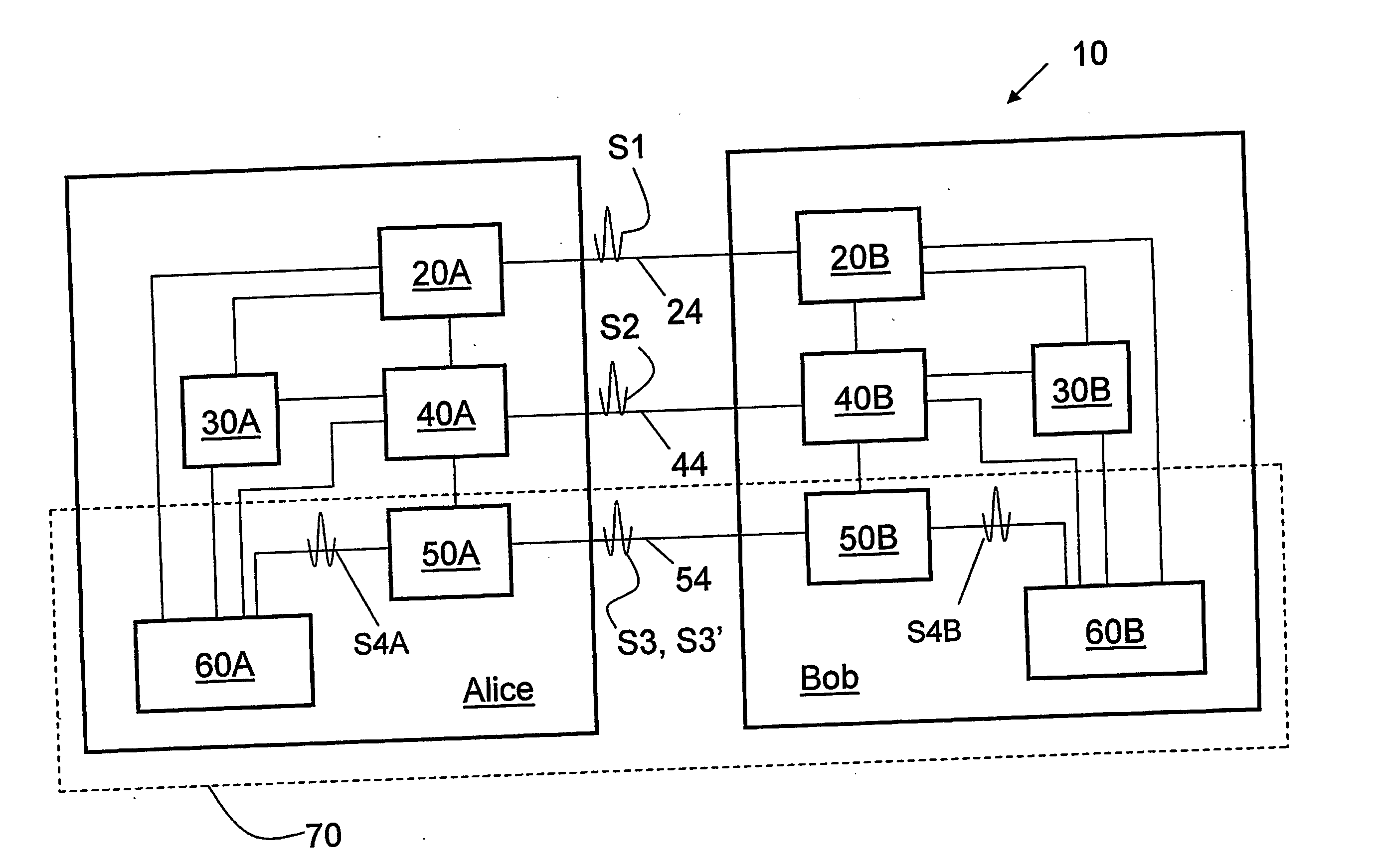
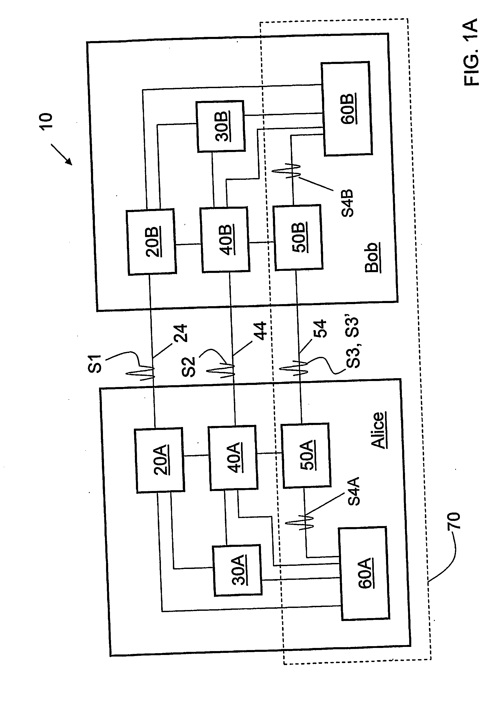
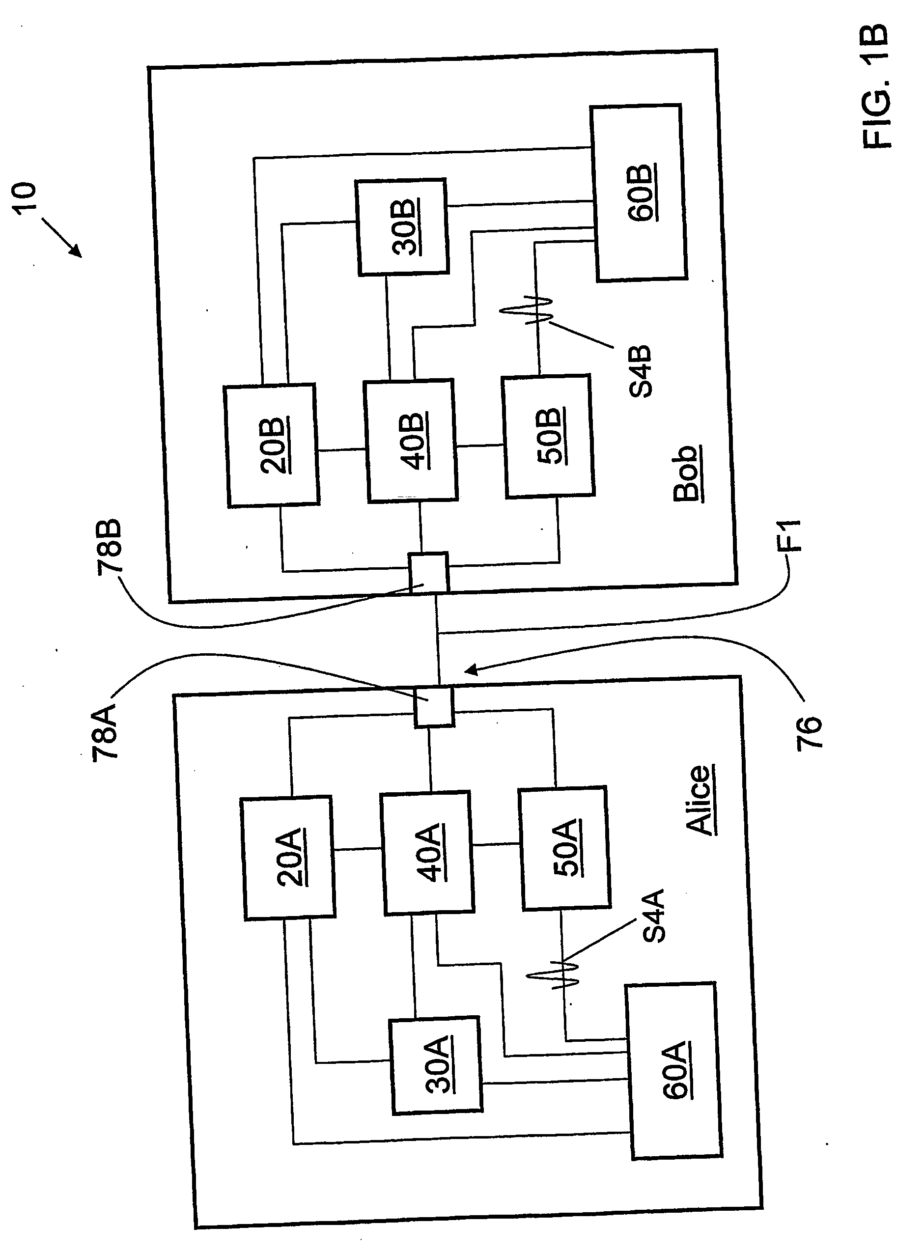
"The present invention relates to a system and method for quantum key distribution (QKD) with robust timing systems and methods. The technical effects of the invention include improved security and efficiency of QKD systems, as well as the ability to operate in a variety of operational modes. The QKD system uses a common transmission medium for the quantum and public channels, and employs a timing system that synchronizes the sending and receiving of optical pulses. The system includes a quantum transceiver for Alice and Bob, each with a random number generator unit and a controller. The quantum transceivers include a WDM in each QKD station and a single communication link for the quantum, data, and timing channels. The invention allows for the manufacture and deployment of commercially viable QKD systems."

Problems solved by technology

As a consequence, an eavesdropper (“Eve”) that attempts to intercept or otherwise measure the quantum signal will inherently introduce errors into the transmitted signals, thereby revealing her presence.
However, the timing systems and methods necessary for practical operation the system are not disclosed in the '410 patent.
Thus, the timing system of the '648 patent operates in a switched mode rather than in a continuous mode, which is not an efficient way to maintain timing synchronization and control jitter in the timing signal.
Further, the system as designed is not programmable to operate in the variety of operational modes needed in the field.
These and other shortcomings of the '648 Patent system are disadvantageous in a commercially viable QKD system.

Method used


Image

  • Kd systems with robust timing
  • Kd systems with robust timing
  • Kd systems with robust timing

Examples


Embodiment Construction

[0029] The present invention relates to quantum cryptography, and in particular relates to QKD systems with robust timing systems and methods for performing QKD. QKD systems have industrial utility only to the extent that they can operate and be adjusted in the field and not just in a laboratory or other artificial environments. To this end, it is critical that a commercially viable QKD system be designed to operate in combination with a robust timing system that allows for the synchronous operation of the various elements of the QKD system. In particular, the QKD system needs to operate in the field so that weak quantum signals can be generated and detected in order to exchange a secure key in a variety of real-world environments.

[0030] An overview of various embodiments of QKD systems according to the present invention is first set forth. This is followed by a more detailed explanation of the structure and operation of example timing systems corresponding to the various modes of ...


PUM


Abstract

QKD systems having timing systems and timing method that allow for QKD to be performed in actual field conditions associated with practical commercial applications of quantum cryptography. The QKD system includes optical modems in each QKD station. Each modem has a circulator with an optical receiver and an optical transmitter coupled to it. One of the optical modems includes two phase lock loops and the other optical modem includes a phase lock loop and a transmit clock. Synchronization pulses are exchanged between the optical modems over a timing channel to synchronize the operation of the QKD system. The phase lock loops serve to lock a receive timing domain to a transmit time domain to ensure proper encoding and detection of weak quantum signals exchanged between the QKD stations.

Description

CLAIM OF PRIORITY [0001] This patent application claims priority from U.S. Provisional Patent Application No. 60 / 445,805, filed on Feb. 7, 2003.TECHNICAL FIELD OF THE INVENTION [0002] The present invention relates to quantum cryptography, and in particular relates to quantum key distribution (QKD) systems with robust timing systems and methods for performing QKD. BACKGROUND ART [0003] Quantum key distribution (QKD) involves establishing a key between a sender (“Alice”) and a receiver (“Bob”) by using weak (e.g., 0.1 photon, on average) optical signals transmitted over a “quantum channel.” The security of the key distribution is based on the quantum mechanical principal that any measurement of a quantum system in an unknown state will modify its state. As a consequence, an eavesdropper (“Eve”) that attempts to intercept or otherwise measure the quantum signal will inherently introduce errors into the transmitted signals, thereby revealing her presence. [0004] The general principles o...

Claims


Application Information

Patent Timeline
Patent Type & Authority Applications(United States)
IPC IPC(8): H04K1/00
CPCH04L9/0852
Inventor VIG, HARRYTRIFONOV, ALEXEICHEN, LIUPING
Owner MAGIQ TECH INC
Learn More