Redundant powered device circuit

a power supply circuit and power supply technology, applied in the direction of current supply arrangements, substation equipment, transmission, etc., can solve the problems of no provision in the above standard for redundancy

Active Publication Date: 2006-01-26
CISCO TECH INC
View PDF17 Cites 56 Cited by
  • Summary
  • Abstract
  • Description
  • Claims
  • Application Information

AI Technical Summary

Benefits of technology

[0010] Accordingly, it is a principal object of the present invention to overcome the disadvantages of prior art. This is provided in the invention by enabling redundant powering of a PD via two PSEs each having a separate path over communication cabling to a PD. In the event of an outage of one of the two PSEs, or of the failure of any portion of the path from one of the two PSEs, power is supplie

Problems solved by technology

Unfortunately, no provision has been made in the above standard for PDs requiring power in excess of the above maximum power requirement.
Furthermore

Method used


Image

  • Redundant powered device circuit
  • Redundant powered device circuit
  • Redundant powered device circuit

Examples


Embodiment Construction

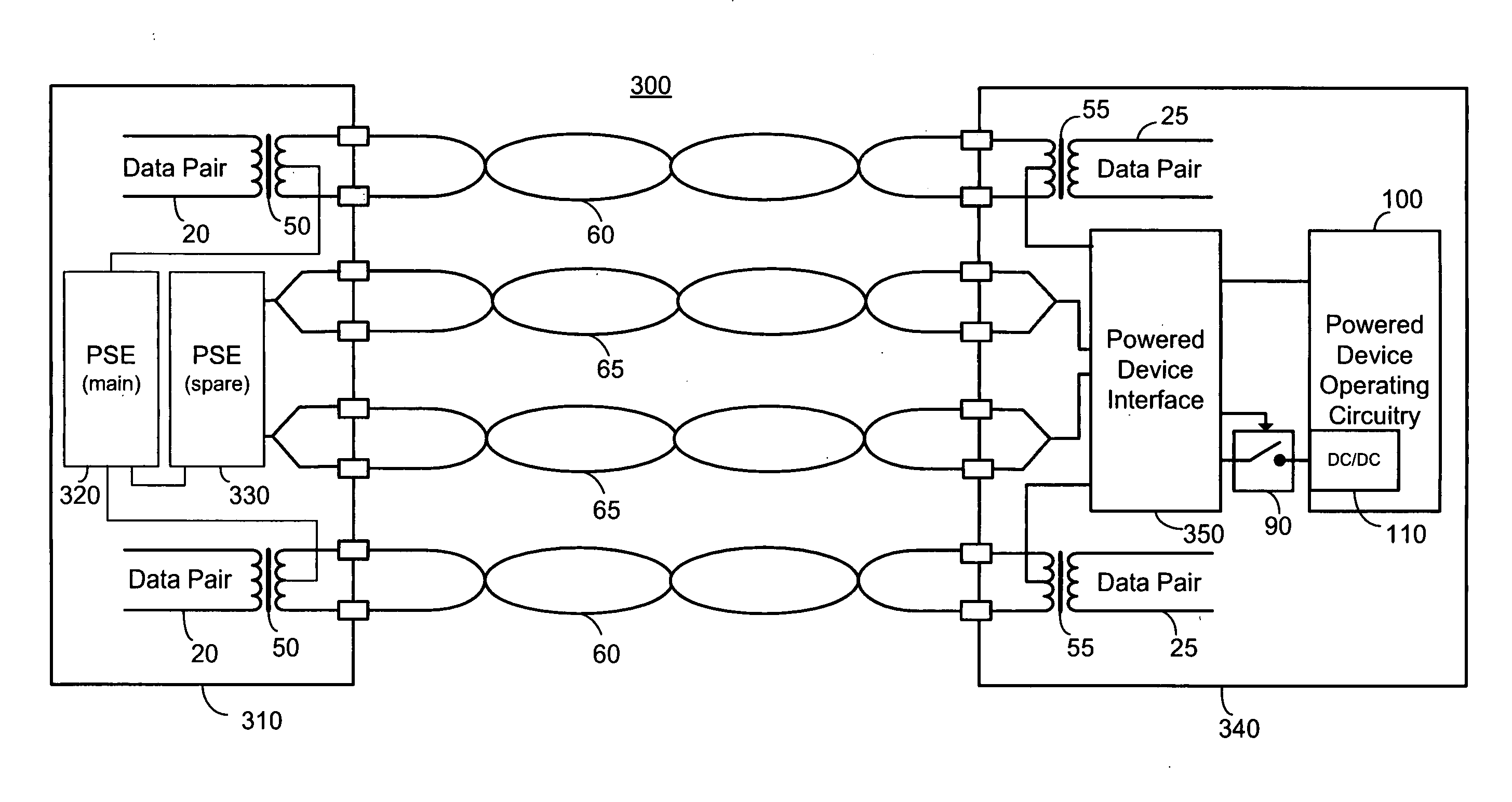
[0040] The present embodiments enable redundant powering of a PD by providing at least two PSEs each having a separate path over communication cabling for powering the PD. In the event of an outage of a first one of the two PSEs, or of the failure of any portion of the path from the first one of the two PSEs, power is supplied by the second of the two PSEs. In one embodiment the second of the two PSEs, operating as a backup, spare, reserve or redundant PSE, receives a valid maintain power signature from the PD thus ensuring availability. In another embodiment the second of the two PSEs receives data regarding the operation of the first PSE, and ensures availability on the back-up path in the absence of a valid maintain power signature. Preferably and advantageously, the redundant PSE exhibits an active power output irrespective of a valid MPS, thus power may be drawn immediately upon failure of the first PSE without requiring a subsequent detection.

[0041] In yet another embodiment ...


PUM


Abstract

A redundant powering system for a powered device receiving power over communication cabling, the redundant powering system comprising: a redundant power supply comprising a first power sourcing equipment and a second power sourcing equipment; a powered device; communication cabling connecting the redundant power supply to the powered device, the communication cabling comprising a first path connecting the first power sourcing equipment to the powered device and a second path connecting the second power sourcing equipment to the powered device, the first and second paths at least partially being constituted of a single structured cable, the at least one powered device comprising at least one signature impedance, the redundant power supply being operable so that power is operably supplied to the powered device from only one of the first and second power sourcing equipment.

Description

CROSS-REFERENCE TO RELATED APPLICATIONS [0001] This application claims priority from U.S. Provisional Patent Application Ser. No. 60 / 608,874 filed Sep. 13, 2004 entitled “Redundant Powered Device Circuit”, the entire contents of which are incorporated herein by reference, and is a continuation-in-part of U.S. patent application Ser. No. 10 / 761,327 filed Jan. 22, 2004 entitled “High Power Architecture for Power over Ethernet”, U.S. patent application Ser. No. 11 / 036,063 filed Jan. 18, 2005 entitled “High Power Architecture for Power over Ethernet”, and U.S. patent application Ser. No. 11 / 053,872 filed Feb. 10, 2005 entitled “HIGH POWER CLASSIFICATION FOR POWER OVER ETHERNET” the entire contents of each of which are incorporated herein by reference.BACKGROUND OF THE INVENTION [0002] The invention relates generally to the field of power over local area networks, particularly Ethernet based networks, and more particularly to a redundant powering system of a device powered over communica...

Claims


Application Information

Patent Timeline
IPC IPC(8): H04M9/00
CPCH04M19/08
Inventor BERSON, YUVALDARSHAN, YAIRKORCHARZ, DRORLEVI, RAANANFERENTZ, ALONATIAS, ILANPINCU, DAVIDELKAYAM, SHIMONPEKER, ARKADIY
Owner CISCO TECH INC
Why Eureka
Try Eureka