Surgical apparatus with a manually actuatable assembly and a method of operating same

Inactive Publication Date: 2006-01-26
MEDTRONIC INC
View PDF4 Cites 1169 Cited by
  • Summary
  • Abstract
  • Description
  • Claims
  • Application Information

AI Technical Summary

Benefits of technology

[0007] The above problems are solved by an embodiment of the present invention, in which the console is eliminated and a manually-actuatable switch assembly is provided that contains a portable source of electrical energy, and is adapted to control the

Problems solved by technology

However, the console is bulky, somewhat complicated to set up, and is not very mobile.
However, the handpiece

Method used


Image

  • Surgical apparatus with a manually actuatable assembly and a method of operating same
  • Surgical apparatus with a manually actuatable assembly and a method of operating same

Examples


Embodiment Construction

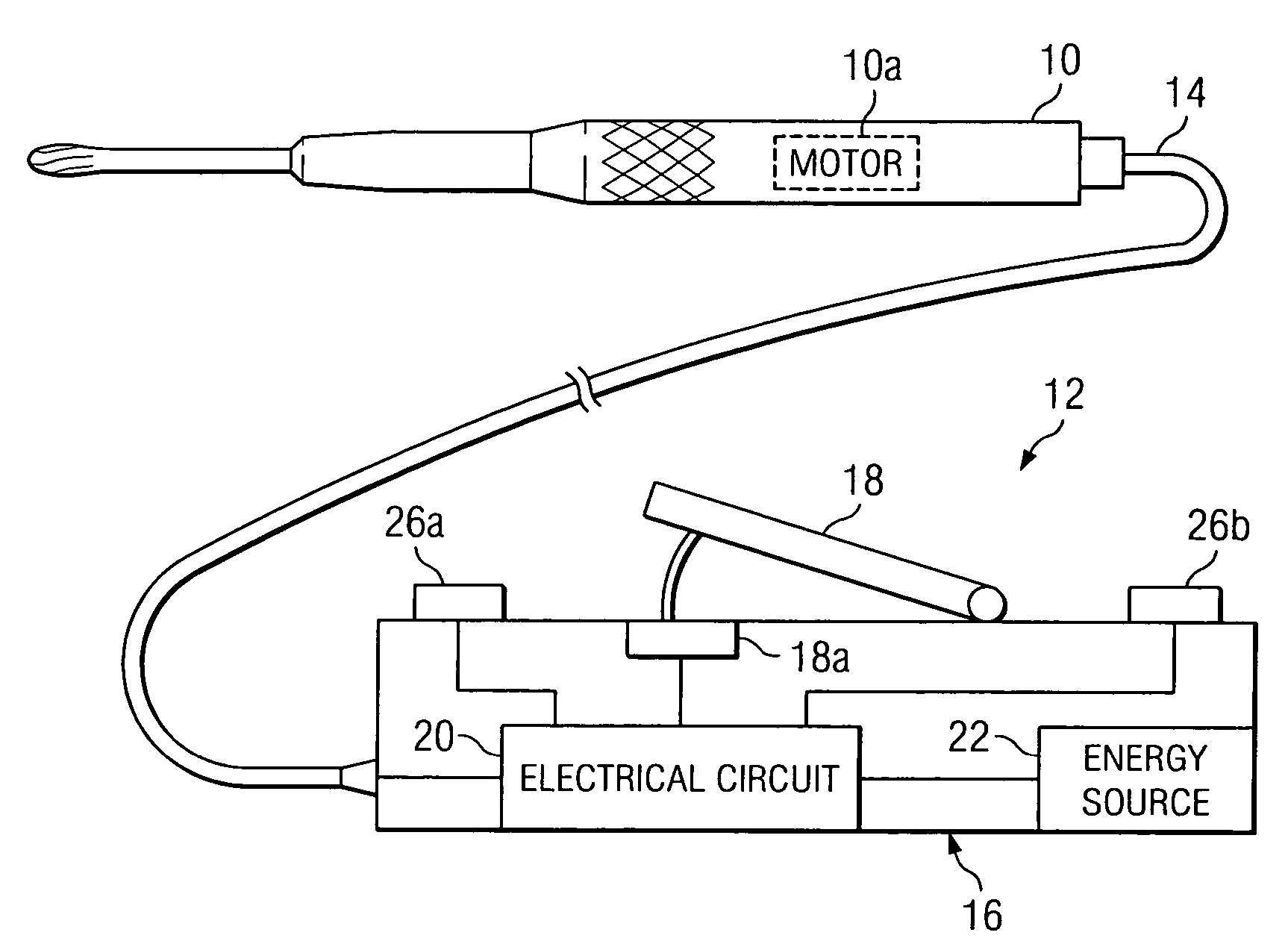
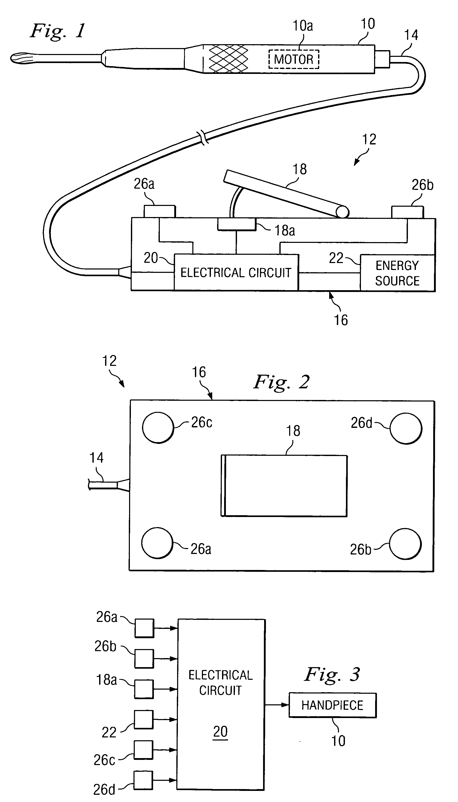
[0012] Referring to FIGS. 1 and 2 of the drawings, the reference 10 refers, in general, to a handpiece in the form of an electrically powered tool for use in surgical procedures, such as the removal or separation of body tissue. The handpiece 10 is driven by an internal electrical motor 10a, and is adapted to receive a cutting accessory (not shown), such as a drill bit, a bur, a saw blade, a reamer, or the like, that can be removably connected to the output shaft of the motor 10a in a conventional manner. When the motor 10a is activated in a manner to be described, the output shaft, and therefore the cutting accessory, are rotated, reciprocated, and / or oscillated at a predetermined speed to enable the surgical procedure to be performed.

[0013] A switch and control assembly 12 is provided for activating the motor 10a and controlling the operation of the handpiece 10 in a manner to be described. An electrical cable assembly 14 is electrically and mechanically connected between the ass...


PUM


Abstract

A surgical tool assembly and a method of operating same according to which a surgical tool is connected to a handpiece having an electrically operated motor; and a portable source of electrical energy is provided in a pedal assembly for controlling the tool. The source is electrically connected to the motor; and the pedal can be engaged for controlling the flow of the electrical energy from the source to the motor.

Description

CROSS-REFERENCE [0001] This application claims priority of provisional application Ser. No. 60 / 589,399, filed Jul. 20, 2004.FIELD OF THE INVENTION [0002] This invention relates to a surgical tool assembly utilizing a manually-controlled switch assembly, and a method of operating same. BACKGROUND [0003] Many surgical tool assemblies include a motorized handpiece to which a cutting accessory, such as a drill bit, bur, saw blade, reamer, or the like, is attached, for removing or separating sections of body tissue. The handpiece is often connected to a separate switch for activating the handpiece, and to a separate, stand-alone, console. The console is connected to a source of AC power and contains electronics that converts the AC line voltage to a voltage suitable for driving and controlling the operation of the handpiece. [0004] However, the console is bulky, somewhat complicated to set up, and is not very mobile. Also, at least two electric cables must be connected between the consol...

Claims


Application Information

Patent Timeline
IPC IPC(8): A61B17/00
CPCA61B17/1626A61B17/1628A61B2017/00973A61B2017/00367A61B2017/00734A61B17/32002
Inventor STRAUSS, PAULFARROW, WADE PHILELLINS, ROB
Owner MEDTRONIC INC
Why Eureka
Try Eureka