Automated annular plication for mitral valve repair

an annular plication and mitral valve technology, applied in the field of automatic annular plication for mitral valve repair, can solve the problems of time-consuming and technical difficulties, no clinically-applicable techniques for performing mitral valve surgery on a beating heart without, and the associated risks of cardiopulmonary bypass. achieve the effect of reducing the regurgitation of the mitral valv

Inactive Publication Date: 2006-01-26
VIACOR INC
View PDF19 Cites 1587 Cited by
  • Summary
  • Abstract
  • Description
  • Claims
  • Application Information

AI Technical Summary

Benefits of technology

[0049] positioning the first anchoring element in the coronary sinus adjacent to the mitral annulus, and positioning the second anchoring element in another area of the mitral ann

Problems solved by technology

This technique can be time-consuming and technically difficult.
It is well-known that cardiopulmonary bypass is associated with significant morbidity and mortality.
To date, however, there are no clinically-applicable techniques for performing mitral valve surgery on a beating heart without the use of a heart-lung machine.
In current practice, all patients judged to be candidates for mitral valve surgery must face the risk of cardiopulmonary bypass and cardiac arrest.
Conversely, other patients (i.e., those with poor

Method used


Image

  • Automated annular plication for mitral valve repair
  • Automated annular plication for mitral valve repair
  • Automated annular plication for mitral valve repair

Examples


Embodiment Construction

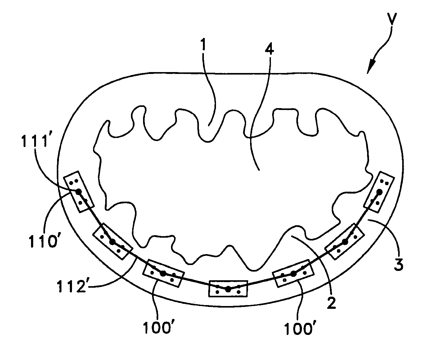
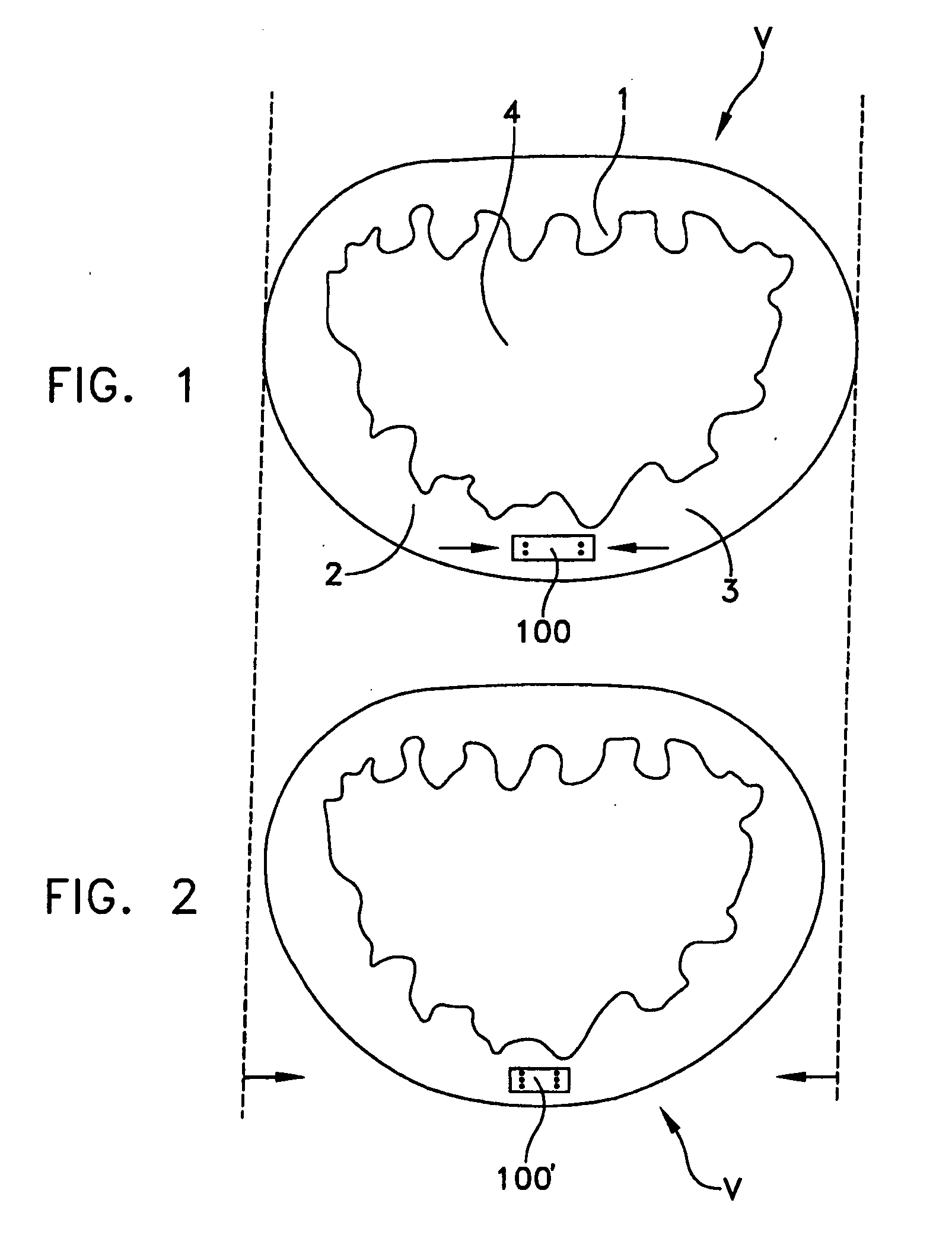
[0086] The plication bands of the present invention allow plication of a valve annulus using one or both of two methods.

[0087] The first method of reducing the valve annulus is by constriction of the plication band itself. Each plication band enters the annulus tissue at two or more points which are spaced from one other by a set distance which is dictated by the geometry of the plication band. Subsequent constriction of the plication band causes these points to move toward each other, thereby constricting the tissue trapped between these points and thus reducing the overall circumference of the valve annulus.

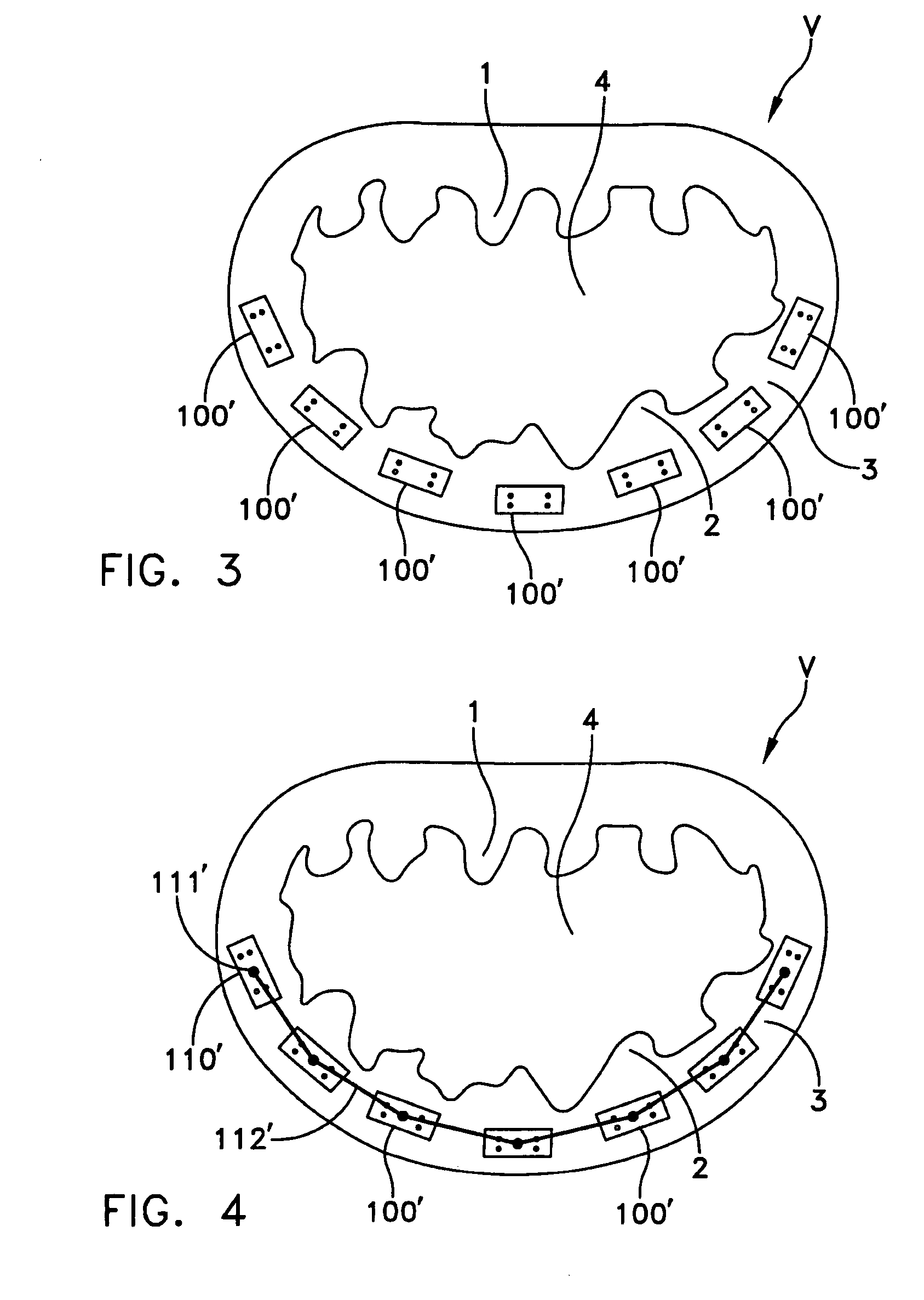
[0088] The second method of reducing the valve annulus is by linking multiple plication bands to one other, using a linkage construct, and then using a shortening of the length of the linkage construct between each plication band so as to gather the tissue between each plication band, whereby to reduce the overall circumference of the valve annulus.

[0089] In one exemplary em...


PUM


Abstract

A method for reducing mitral regurgitation comprising: providing a plication assembly comprising a first anchoring element, a second anchoring element, and a linkage construct connecting the first anchoring element to the second anchoring element; positioning the first anchoring element in the coronary sinus adjacent to the mitral annulus, and positioning the second anchoring element in another area of the mitral annulus so that the linkage construct extends across the opening of the mitral valve and holds the mitral valve in a reconfigured configuration so as to reduce mitral regurgitation. An apparatus for reducing mitral regurgitation comprising: a plication assembly comprising a first anchoring element, a second anchoring element, and a linkage construct connecting the first anchoring element to the second anchoring element; and a catheter adapted to deliver the first anchoring element to the coronary sinus.

Description

REFERENCE TO PENDING PRIOR PATENT APPLICATIONS [0001] This is a continuation-in-part of pending prior U.S. patent application Ser. No. 10 / 004,474, filed Oct. 23, 2001 by John R. Liddicoat et al. for AUTOMATED ANNULAR PLICATION FOR MITRAL VALVE REPAIR (Attorney's Docket No. VIA-12). [0002] This patent application also claims benefit of pending prior U.S. Provisional Patent Application Ser. No. 60 / 543,514, filed Feb. 11, 2004 by John R. Liddicoat for AUTOMATED ANNULAR PLICATION FOR MITRAL VALVE REPAIR (Attorney's Docket No. VIA-47 PROV).[0003] The aforementioned two patent applications are hereby incorporated herein by reference. BACKGROUND OF THE INVENTION [0004] Mitral valve repair is the procedure of choice to correct mitral regurgitation of all etiologies. With the use of current surgical techniques, between approximately 70% and 95% of regurgitant mitral valves can be repaired. The advantages of mitral valve repair over mitral valve replacement are well-documented. These include ...

Claims


Application Information

Patent Timeline
IPC IPC(8): A61F2/24
CPCA61B17/0644A61B17/0684A61B2017/00243A61F2/2487A61F2/2445A61F2/2451A61B2017/0641
Inventor LIDDICOAT, JOHN R.
Owner VIACOR INC
Why Eureka
Try Eureka