Method and apparatus for improving mitral valve function

Inactive Publication Date: 2007-03-06
GUIDED DELIVERY SYST INC
View PDF82 Cites 307 Cited by
  • Summary
  • Abstract
  • Description
  • Claims
  • Application Information

AI Technical Summary

Benefits of technology

[0029]In another form of the invention, there is provided a method for reducing mitral regurgitation comprising: inserting a straight, substantially rigid elongated body into the coronary sinus of a patient in the vicinity of the posterior leaflet of the mitral valve, the length of the straight, substantially rigid elongated body being sized relative to the natural curvature of the coronary sinus in the vicinity of the posterior leaflet of the mitral valve so that when the straight, substantially rigid elongated body is positioned in the coronary sinus, it will cause at least a portion of the coronary sinus to assume a substantially straight configuration adjacent to the posterior leaflet of the mitral valve, whereby to increase the radius of curvature of the mitral annulus and thereby improve leaflet coaptation.
[0030]In another form of the invention, there is provided an apparatus for reducing mitral regurgitation comprising: a body having a distal end, a proximal end and an intermediate portion, the body being configured so that when the body is positioned in the coronary sinus in the vicinity of the posterior leaflet of the mitral valve, the distal and proximal ends will apply a posteriorly-directed force to the walls of the coronary sinus, and the intermediate portion will apply an anteriorly-directed force to the walls of the coronary sinus, whereby to move the posterior annulus of the mitral valve anteriorly and thereby improve leaflet coaptation.
[0031]In another form of the invention, there is provided an apparatus for reducing mitral regurgitation comprising: a substantially straight elongated body adapted to be inserted into the coronary sinus of a patient in the vicinity of the posterior leaflet of the mitral valve, the length of the substantially straight elongated body being sized relative to the natural curvature of the coronary sinus in the vicinity of the posterior leaflet of the mitral valve so that when the substantially straight elongated body is positioned in the coronary sinus, it will cause at least a portion of

Problems solved by technology

Such a procedure is associated with high morbidity and mortality.
Due to the risks associated with this procedure, many of the sickest patients are denied the potential benefits of surgical correction of mitral regurgitation.
In addition, patients with moderate, symptomatic mitral regurgitation are denied early intervention and undergo surgical correction only after the development of cardiac dysfunction.
Mitral regurgitation is a common occurrence in patients with heart failure and a source of important morbidity and mortality in these patients.
These geometric alterations result in incomplete coaptation of the

Method used


Image

  • Method and apparatus for improving mitral valve function
  • Method and apparatus for improving mitral valve function
  • Method and apparatus for improving mitral valve function

Examples


Embodiment Construction

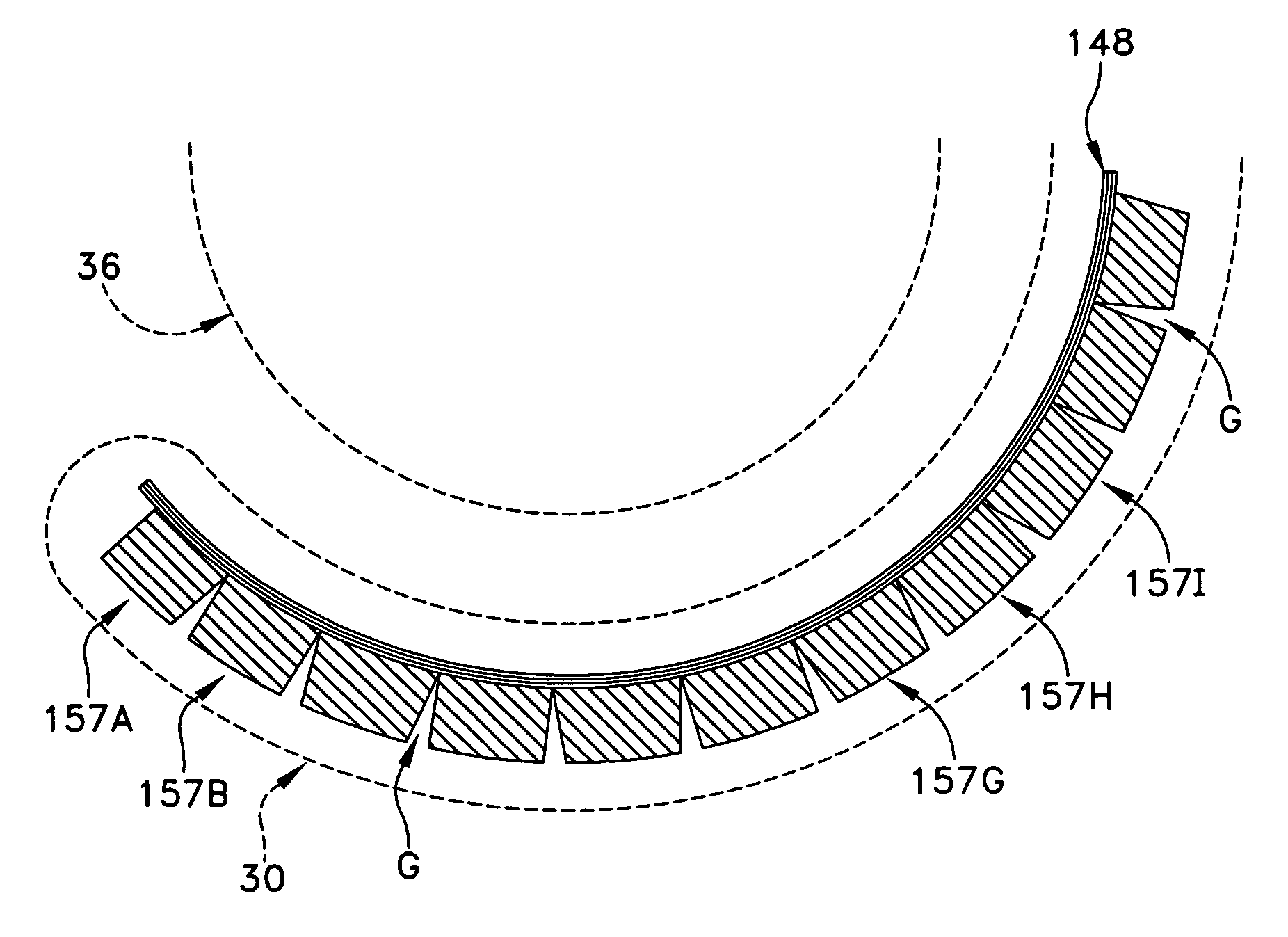
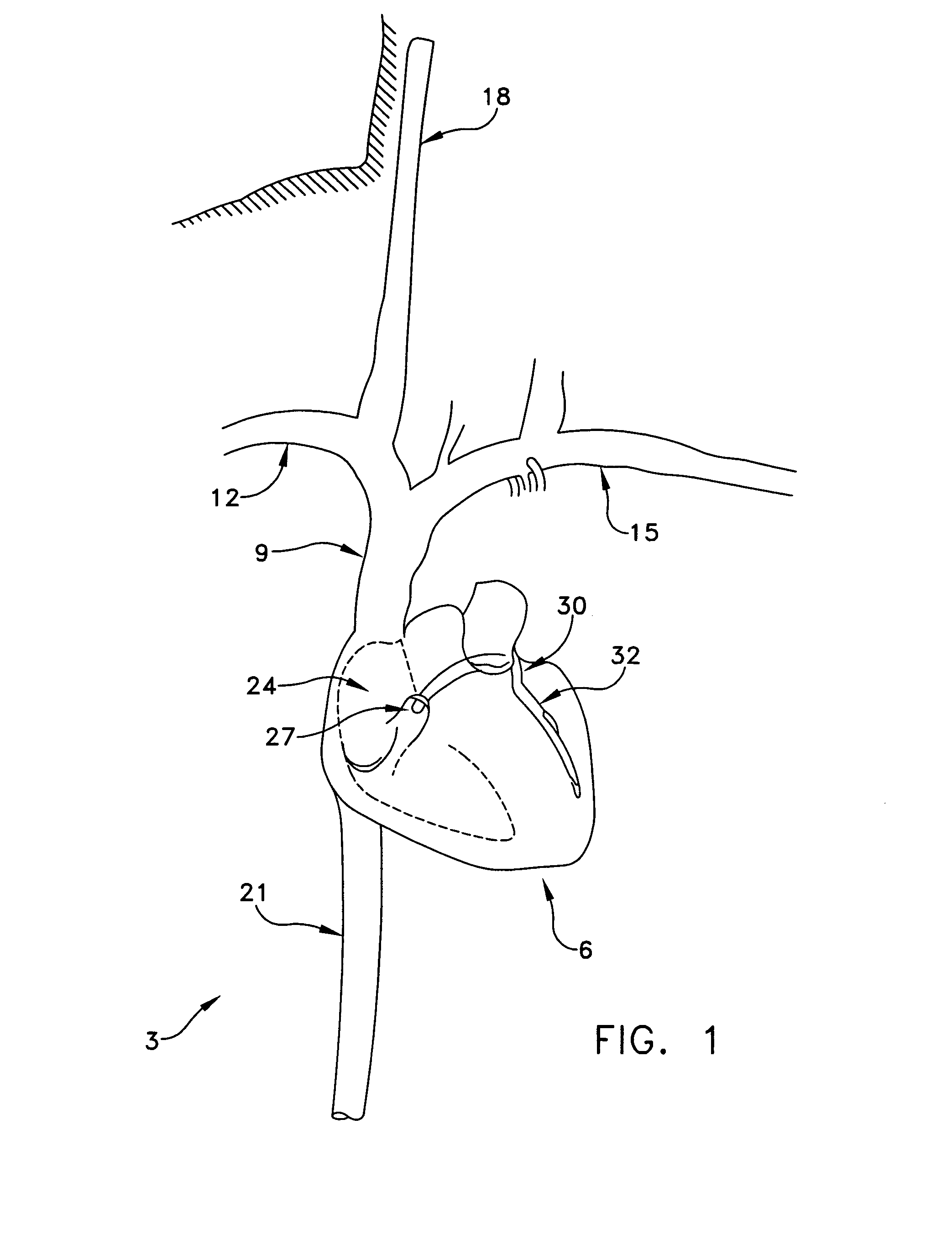
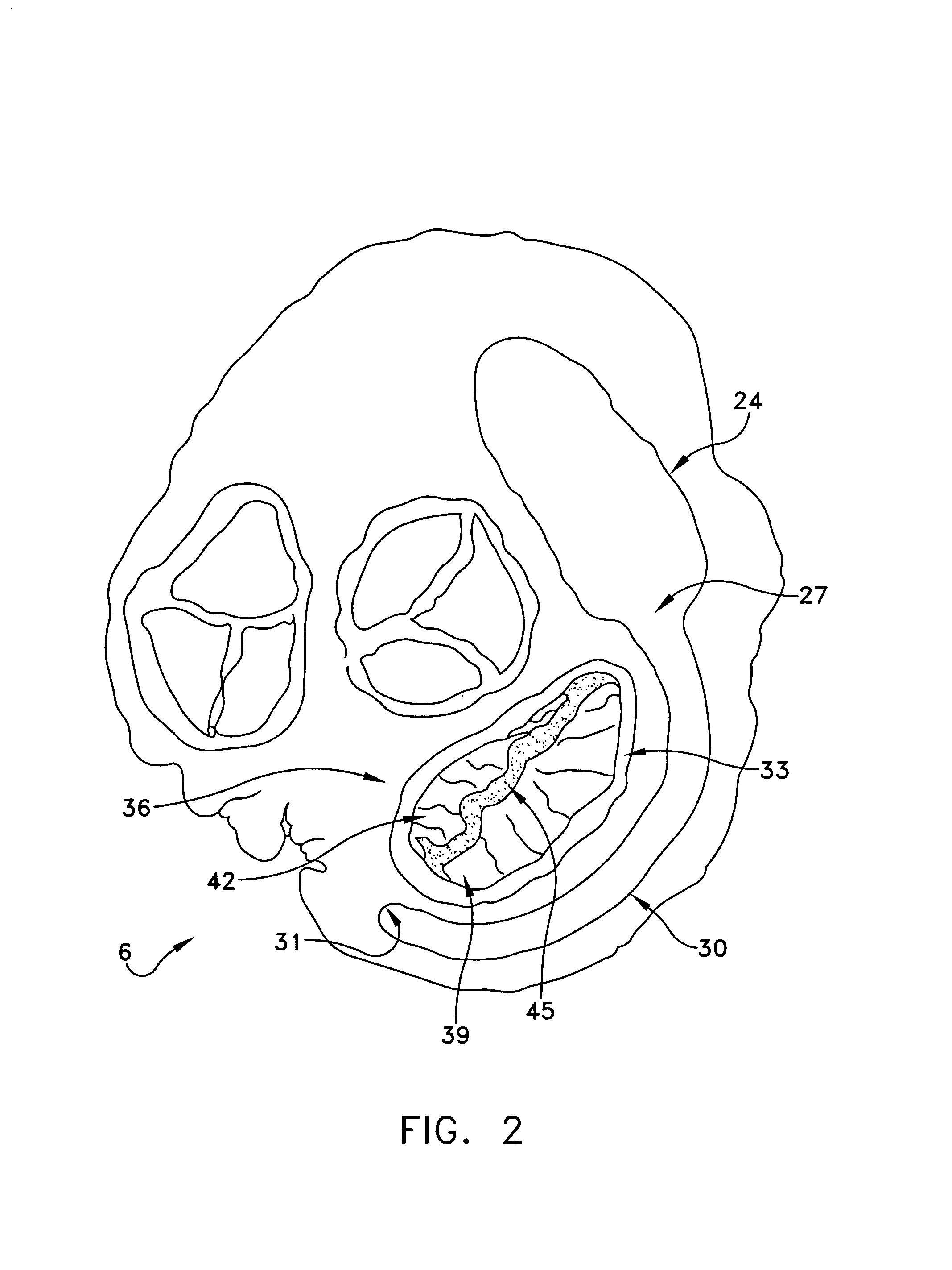
[0065]The coronary sinus is the largest vein in the human heart. During a large portion of its course in the atrioventricular groove, the coronary sinus typically extends adjacent to the left atrium of the heart for a distance of approximately 5 to 10 centimeters. Significantly, for a portion of its length, e.g., typically approximately 7–9 cm, the coronary sinus extends substantially adjacent to the posterior perimeter of the mitral annulus. The present invention takes advantage of this consistent anatomic relationship. More particularly, by deploying novel apparatus in the coronary sinus, adjacent to the posterior leaflet of the mitral valve, the natural curvature of the coronary sinus may be modified in the vicinity of the posterior leaflet of the mitral valve, whereby to move the posterior annulus anteriorly so as to improve leaflet coaptation and, as a result, reduce mitral regurgitation.

[0066]In one preferred embodiment of the invention, the novel apparatus comprises a straigh...


PUM


Abstract

A method and apparatus for reducing mitral regurgitation. The apparatus is inserted into the coronary sinus of a patient in the vicinity of the posterior leaflet of the mitral valve, the apparatus being adapted to straighten the natural curvature of at least a portion of the coronary sinus in the vicinity of the posterior leaflet of the mitral valve, whereby to move the posterior annulus anteriorly and thereby improve leaflet coaptation and reduce mitral regurgitation.

Description

REFERENCE TO PENDING PRIOR PATENT APPLICATIONS[0001]This patent application:[0002](1) is a continuation-in-part of prior U.S. patent application Ser. No. 10 / 068,264, filed Feb. 5, 2002 now U.S. Pat. No. 6,656,221 by Daniel C. Taylor et al. for METHOD AND APPARATUS FOR IMPROVING MITRAL VALVE FUNCTION;[0003](2) claims benefit of pending prior U.S. Provisional Patent Application Ser. No. 60 / 279,974, filed Mar. 29, 2001 by Daniel C. Taylor et al. for METHOD AND APPARATUS TO IMPROVE MITRAL VALVE FUNCTION.[0004](3) claims benefit of pending prior U.S. Provisional Patent Application Ser. No. 60 / 280,038, filed Mar. 30, 2001 by William E. Cohn et al. for METHODS AND APPARATUS FOR TEMPORARY IMPROVEMENT IN MITRAL VALVE FUNCTION;[0005](4) claims benefit of pending prior U.S. Provisional Patent Application Ser. No. 60 / 279,973, filed Mar. 29, 2001 by Daniel C. Taylor et al. for METHODS AND DEVICES TO IMPROVE MITRAL VALVE FUNCTION;[0006](5) claims benefit of pending prior U.S. Provisional Patent A...

Claims


Application Information

Patent Timeline
IPC IPC(8): A61F2/24
CPCA61F2/2451Y10S623/903Y10S623/904A61F2/2466
Inventor LIDDICOAT, JOHN R.TAYLOR, DANIEL C.STREETER, RICHARD B.WOOLFSON, STEVEN B.COHN, WILLIAM E.DAVENPORT, TODD F.
Owner GUIDED DELIVERY SYST INC
Why Eureka
Try Eureka