
Facet-preserving artificial disc replacements

a technology of artificial discs and facets, which is applied in the field of artificial disc replacements with facetpreserving features, can solve the problems of low back pain, reduced risk of separation of adrs from vertebrae above and below, and may not provide sufficient distraction across the disc space by themselves, so as to reduce the load on the facet joints, limit axial rotation, and limit lateral bending

Inactive Publication Date: 2006-01-26
FERREE BRET A +2
View PDF61 Cites 191 Cited by
  • Summary
  • Abstract
  • Description
  • Claims
  • Application Information

AI Technical Summary

Benefits of technology

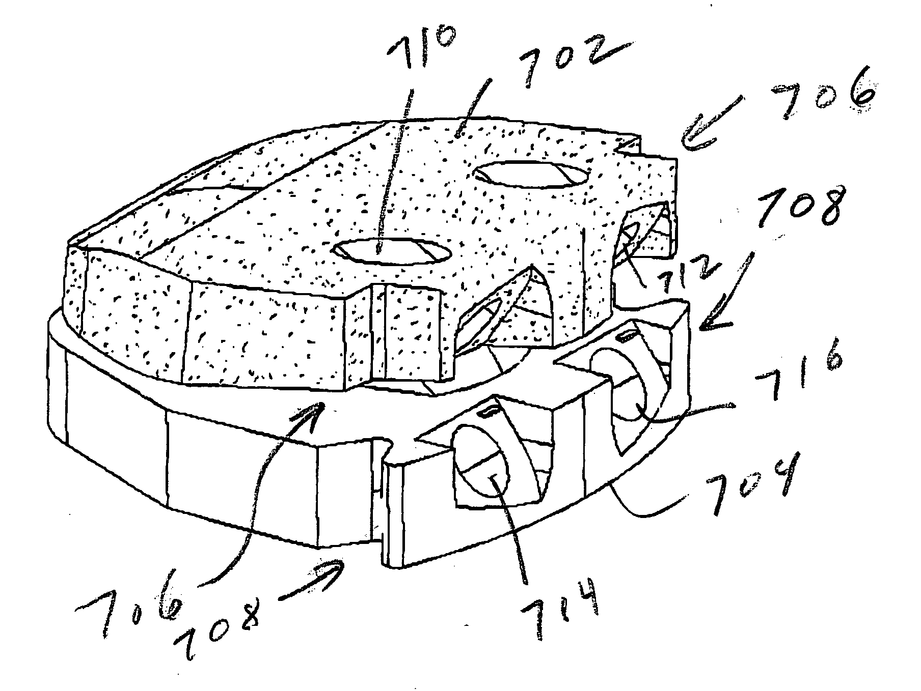
[0011] This invention resides in artificial disc replacement (ADRs) offering various advantages, including a reduction of loading on the facet joints. The various components cooperate to limit axial rotation and to limit lateral bending to a greater degree when the spine is extended than when the spine is a neutral to flexed position. Limiting axial rotation and lateral bending of the TDR protects the facet joints and the Annulus Fibrosus since the facet joints carry more load when the spine is extended than when the spine is flexed. Thus, the invention decreases the loads placed upon the facet joints to protect the facet joints, while allowing normal or near-normal spinal motion.

Problems solved by technology

Motion across arthritic facet joints could lead to pain following ADR.
In fact, ADRs of this kind may not, by themselves, provide sufficient distraction across the disc space.
Replicating the movements of the natural disc also decreases the risk of separation of the ADR from the vertebrae above and below the ADR.
Arthritic facet joints may cause low back pain.
In fact, the increased spinal motion following ADR may increase the loads on the facet joints.

Method used


Image

  • Facet-preserving artificial disc replacements
  • Facet-preserving artificial disc replacements
  • Facet-preserving artificial disc replacements

Examples


Embodiment Construction

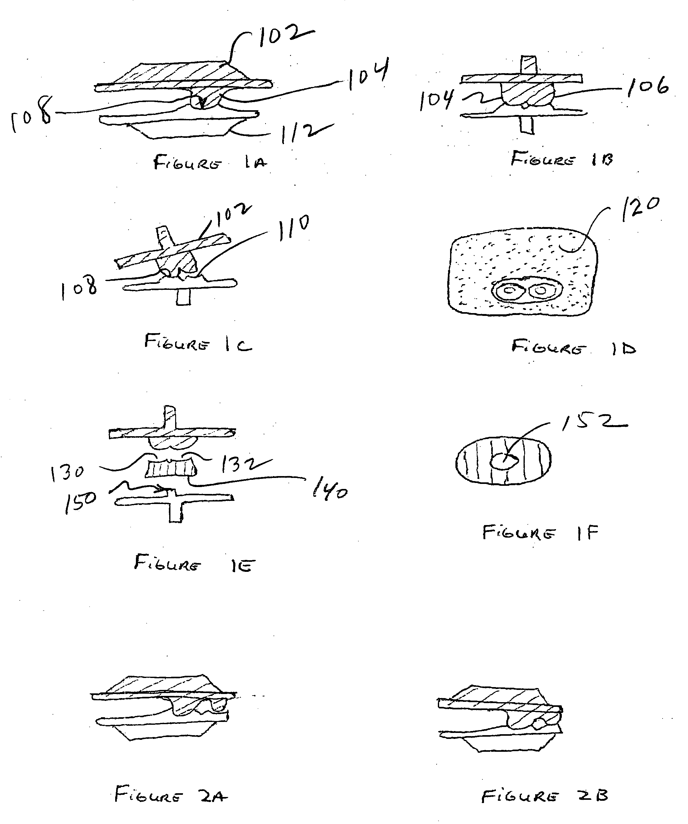
[0070]FIG. 1A is a lateral view of a two-component ADR according to the invention. The superior component 102 includes a set of laterally spaced projections 104, 106 that co-act with respective concavities 108, 110 in an inferior component 112. FIG. 1B is an anterior view of the ADR drawn in FIG. 1A. FIG. 1C is an anterior view of the ADR drawn in FIG. 1B, showing how the ADR facilitates lateral bending of the spine. The ADR articulates in the adjacent convexity and concavity when the ADR allows lateral bending to the opposite side. The ADR articulates through both sets of concavities and concavities during flexion and extension while resisting axial rotation.

[0071]FIG. 1D is a view of the top of the inferior ADR endplate (EP) drawn in FIG. 1A. Area 120 represents a cushion material. This embodiment of the ADR is similar to the ADR taught in my co-pending application U.S. Ser. No. 10 / 434,930 (see FIG. 10B). The restricted motion of the ADR helps protect the cushion material. The cu...


PUM


Abstract

Artificial disc replacement (ADR) components cooperate to limit axial rotation and / or lateral bending to a greater degree when the spine is extended than when the spine is a neutral to flexed position, thereby decreasing loads placed upon the facet joints. In the preferred embodiment, truncated articulating surfaces with non-articulating side surfaces allow increasing amounts of axial rotation and lateral bending as the total disc replacement (TDR) moves from full extension to full flexion. Limiting axial rotation and lateral bending of the TDR protects the facet joints and the Annulus Fibrosus, since the facet joints carry more load when the spine is extended than when the spine is flexed. Thus the invention serves to protect the facet joints while allowing normal or near-normal spinal motion.

Description

REFERENCE TO RELATED APPLICATION [0001] This application claims priority from U.S. Provisional Patent Application Ser. No. 60 / 589,702, filed Jul. 21, 2004, the entire content of which is incorporated herein by reference.FIELD OF THE INVENTION [0002] This invention relates generally to artificial intervertebral disc replacement (ADR) and, in particular, to ADRs with facet-preserving features. BACKGROUND OF THE INVENTION [0003] Eighty-five percent of the population will experience low back pain at some point. Fortunately, the majority of people recover from their back pain with a combination of benign neglect, rest, exercise, medication, physical therapy, or chiropractic care. A small percent of the population will suffer chronic low back pain. The cost of treatment of patients with spinal disorders plus the patient's lost productivity is estimated at 25 to 100 billion dollars annually. [0004] Seven cervical (neck), 12 thoracic, and 5 lumbar (low back) vertebrae form the normal human ...

Claims


Application Information

Patent Timeline
Patent Type & Authority Applications(United States)
IPC IPC(8): A61F2/44
CPCA61B17/1757A61B17/1671A61B2017/0256A61B2017/8655A61F2/4425A61F2002/30112A61F2002/30245A61F2002/30365A61F2002/30369A61F2002/30563A61F2002/30662A61F2002/30934A61F2002/443A61F2002/4622A61F2220/0033A61F2230/0004A61F2230/0071A61B17/1659A61B17/8605
Inventor FERREE, BRET A.TOMPKINS, DAVIDFERREE, ALEX B.
Owner FERREE BRET A
Learn More