
Eureka
For R&D, Eureka makes reading and utilizing patents & technical documents easy.
Eureka AIR
Designed for self-driven R&D workflows. Generate viable solutions, solve complex R&D challenges, empower your innovation with AI.

Eureka Materials
Designed for material experts only. Revolutionize your material R&D, from search, analyze, to developing new materials.

TechResearch
Generate reliable direction feasibility study reports for your R&D in just a few steps.

TechSeek
Discover and master advanced knowledge NOW. Basics, ideas, possibilities, all at once.

TechMind
As an expert in R&D Theories, TechMind can generates customized viable solutions instantly.

TechRisk
Analyze your overall solution with one click, know your potential R&D risks in advance.

TechMonitor
Get weekly tech updates, stay abreast of the latest tech innovations and key insights.
Keyboard device for keyboard instrument
- Summary
- Abstract
- Description
- Claims
- Application Information
AI Technical Summary
Benefits of technology
Problems solved by technology
Method used
Image


Examples
first embodiment
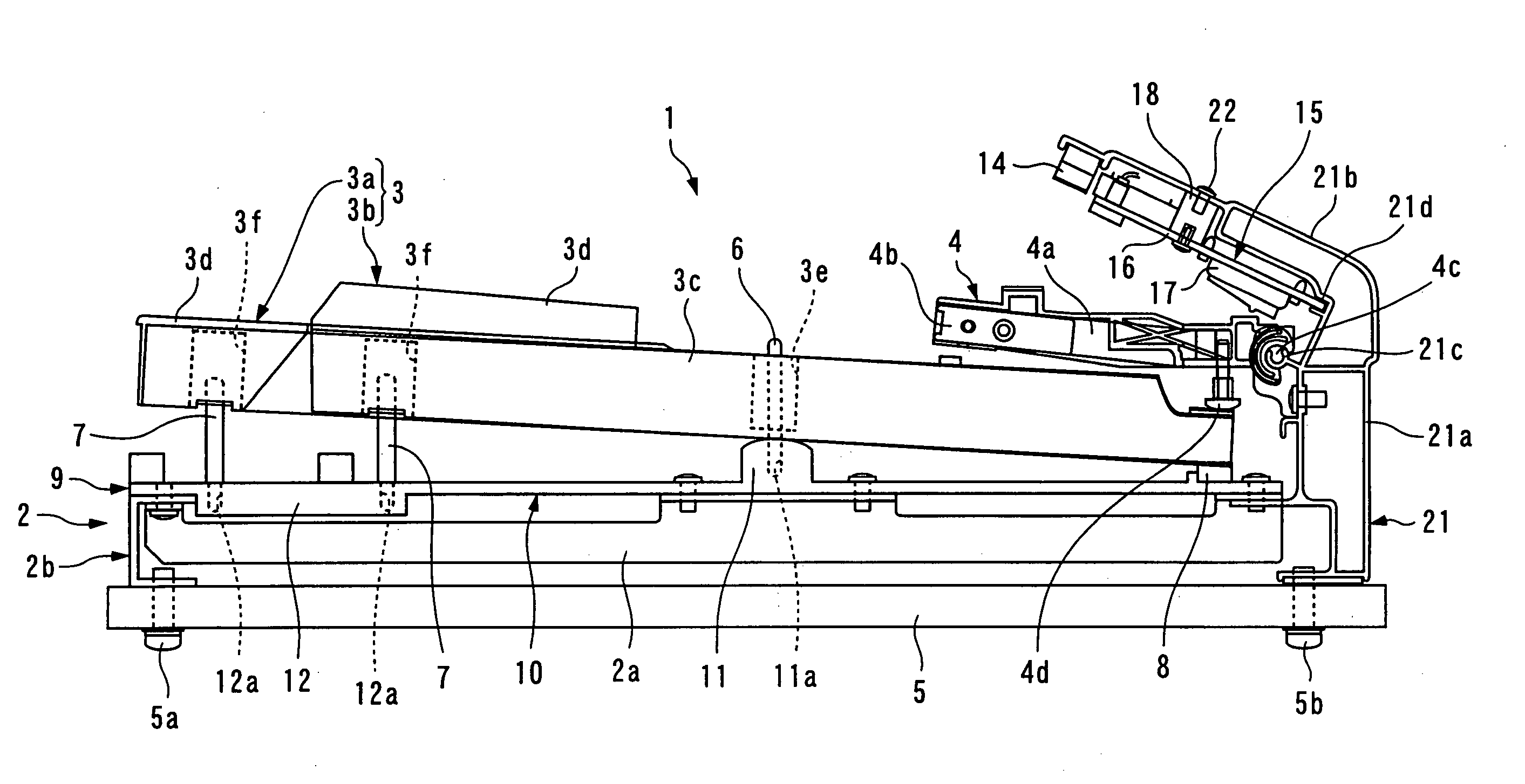
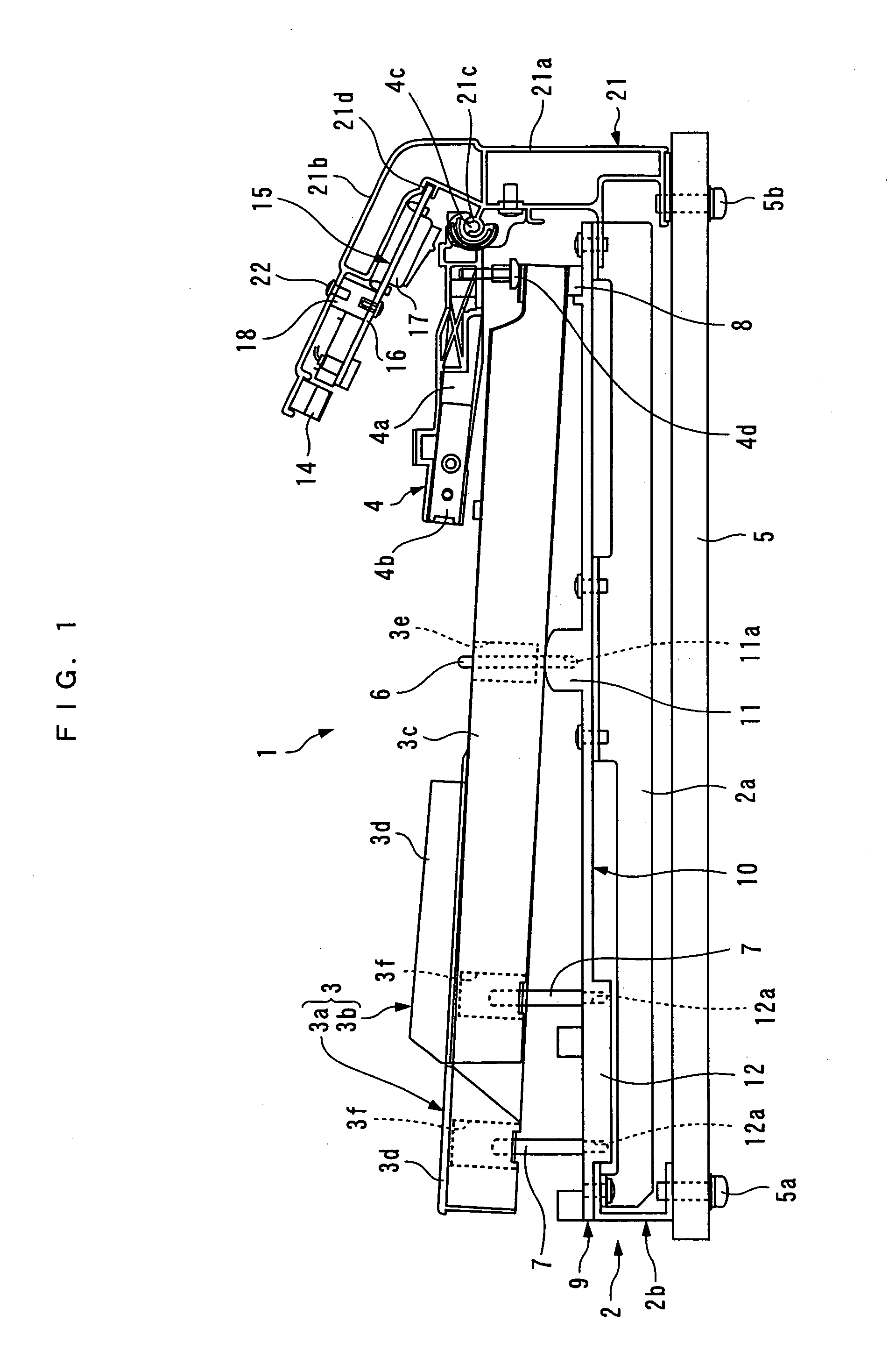
[0047] The invention will now be described in detail with reference to the drawings showing preferred embodiments thereof. FIG. 1 shows a keyboard device for an electronic piano, according to the present invention, in a key-release position. The keyboard device 1 is comprised of a chassis assembly 2, a multiplicity of keys 3 mounted on the chassis assembly 2, in a manner arranged side by side in a left-right direction (in a direction of depth in FIG. 1), and a multiplicity of hammers 4 each of which is pivotally moved according to depression of the associated key.
[0048] The chassis assembly 2 is comprised of a keyframe 9, and a plurality of ribs 2a (only one of which is shown). The keyframe 9 is formed by a molded piece of a synthetic resin integrally formed as a unitary member e.g. by injection molding, and horizontally extents over a full range of notes. The keyframe 9 includes a keyframe body 10, a keyframe center 11, and a keyframe front 12. The keyframe body 10 has a generally ...
second embodiment
[0075] As is distinct from the keyboard device 30 in which the keyframes 3 are provided on the keybed 5 via the chassis 31, in the present embodiment, the construction of the chassis 31 is largely simplified. More specifically, the keyframe body 35 and the ribs 33 are omitted, whereby a keyframe center 52, a keyframe front 53, and the base section 39 are directly mounted on a keybed 51.
[0076] The keybed 51 is made e.g. of MDF (Medium Density Fireboard), and hence it has high shape retention against environmental changes, such as changes in humidity. The keybed 51 has the keyframe center 52 fixed to a central portion thereof in the left-right direction, the keyframe front 53 to an front end thereof, and the base section 39 to a rear end thereof.
[0077] Further, the keyframe center 52 and the keyframe front 53 also have a balance rail pin recess 52a and a front rail pin recess 53a formed therein, respectively, for each key, and the balance rail pin 6 and the front rail pin 7 are pres...
PUM
 Abstract
Description
Claims
Application Information
 - R&D Engineer
- R&D Manager
- IP Professional
- Industry Leading Data Capabilities
- Powerful AI technology
- Patent DNA Extraction
Browse by: Latest US Patents, China's latest patents, Technical Efficacy Thesaurus, Application Domain, Technology Topic, Popular Technical Reports.
© 2024 PatSnap. All rights reserved.Legal|Privacy policy|Modern Slavery Act Transparency Statement|Sitemap|About US| Contact US: help@patsnap.com