Heat exchanger having a double baffle

Active Publication Date: 2006-02-02
VALEO INC
View PDF11 Cites 20 Cited by
  • Summary
  • Abstract
  • Description
  • Claims
  • Application Information

AI Technical Summary

Benefits of technology

[0011] In preferred embodiments of the present invention, it is a further object not only to solve the problem of separation of fluids and prevention of contamination, but also potential problems of inefficient or less effective functioning of baffles caused by temporary blockages of the gap or space normally open to the atmosphere outside of the heat exchanger. In more preferred embodiments of the present invention, the present invention provides for a heat exchanger comprising a single piece double baffle, wherein the double baffle design allows for a sufficient gap to allow leaks to atmosphere, while also being cost effective and relatively easy to manufacture and assemble. SUMMARY OF THE INVENTION
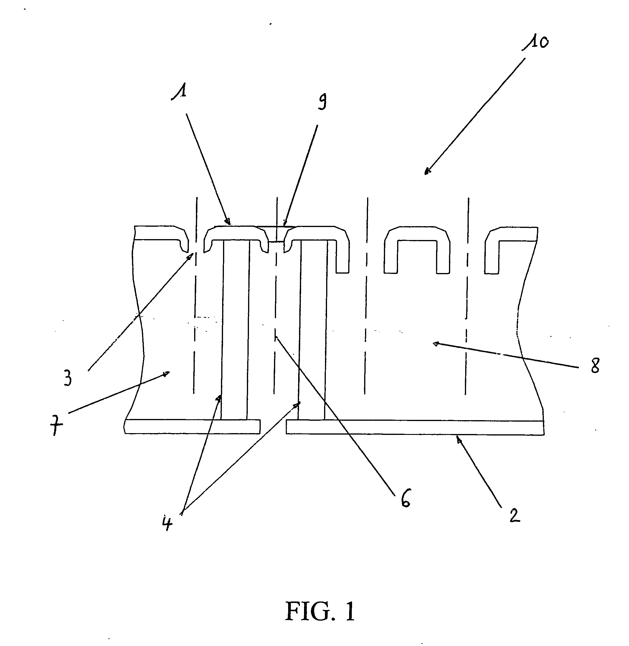
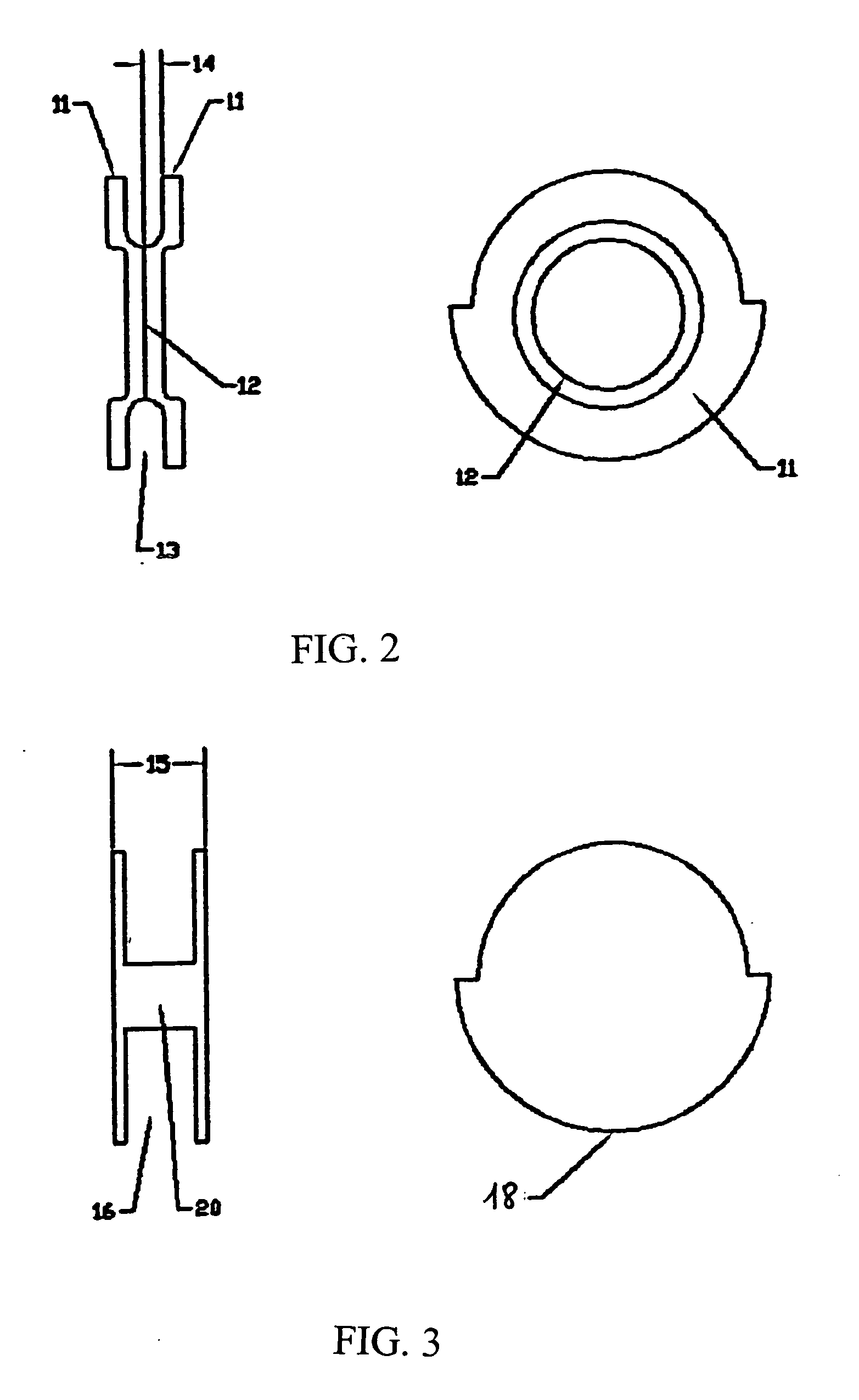
[0019] Preferably, the single piece double baffle provides a shape that can be held easily by tooling to allow the precise and automatic assembly into the manifold assembly. This shape, in addition to the need for only one part, allows for automatic assembly of the part, or greatly improved manual assembly of the part. In particularly preferred embodiments of the present invention, a wider portion of a single piece double baffle beyond the tube walls provides for the largest gap possible between the two separate heat exchanger sections that can be used to advantage.

Problems solved by technology

However, until the present invention, double baffle designs have often resulted in space problems, and the like, contributing to the loss of function or efficiency of one or more of the heat exchanger tubes.
In particular, certain heat exchanger assemblies may have space requirements that extend to at least one core tube-end in the tank.
This has caused a problem, however, since the double piece double baffle needs to be affixed in some manner to maintain its position to perform their function, and positional control needs to be optimized to allow for reduced tube pitches, especially in higher performance heat exchanger assembly applications.
As disclosed above, it has been found that leaks and mixing or contamination between fluids can lead to inefficient or less that optimal heat exchanger performance, as well as damage to the vehicle and customer discomfort.
There are problems with heat exchanger designs, and especially heat exchanger designs that employ multiple baffles, as some of the designs solve the problem of leaks by allowing leaks to the atmosphere; while subsequently providing for two separate baffles with spaces in-between to avoid the problem of leaks between the parts of the exchanger.
However, such designs either take up a large amount of space (EP0789213) or do not allow an adequate gap or space to efficiently function.
In addition, the gaps or spaces between the baffles are susceptible to filling with flux and / or braze materials during manufacture during the braze cycle.
The result of such gap filling can lead to temporary blockages of the gap or space, meaning that the fluids, in case of leak at the double baffle, cannot leak through the gap or space into the atmosphere, and, therefore, lead to inefficient or less effective functioning.

Method used


Image

  • Heat exchanger having a double baffle
  • Heat exchanger having a double baffle
  • Heat exchanger having a double baffle

Examples


Embodiment Construction

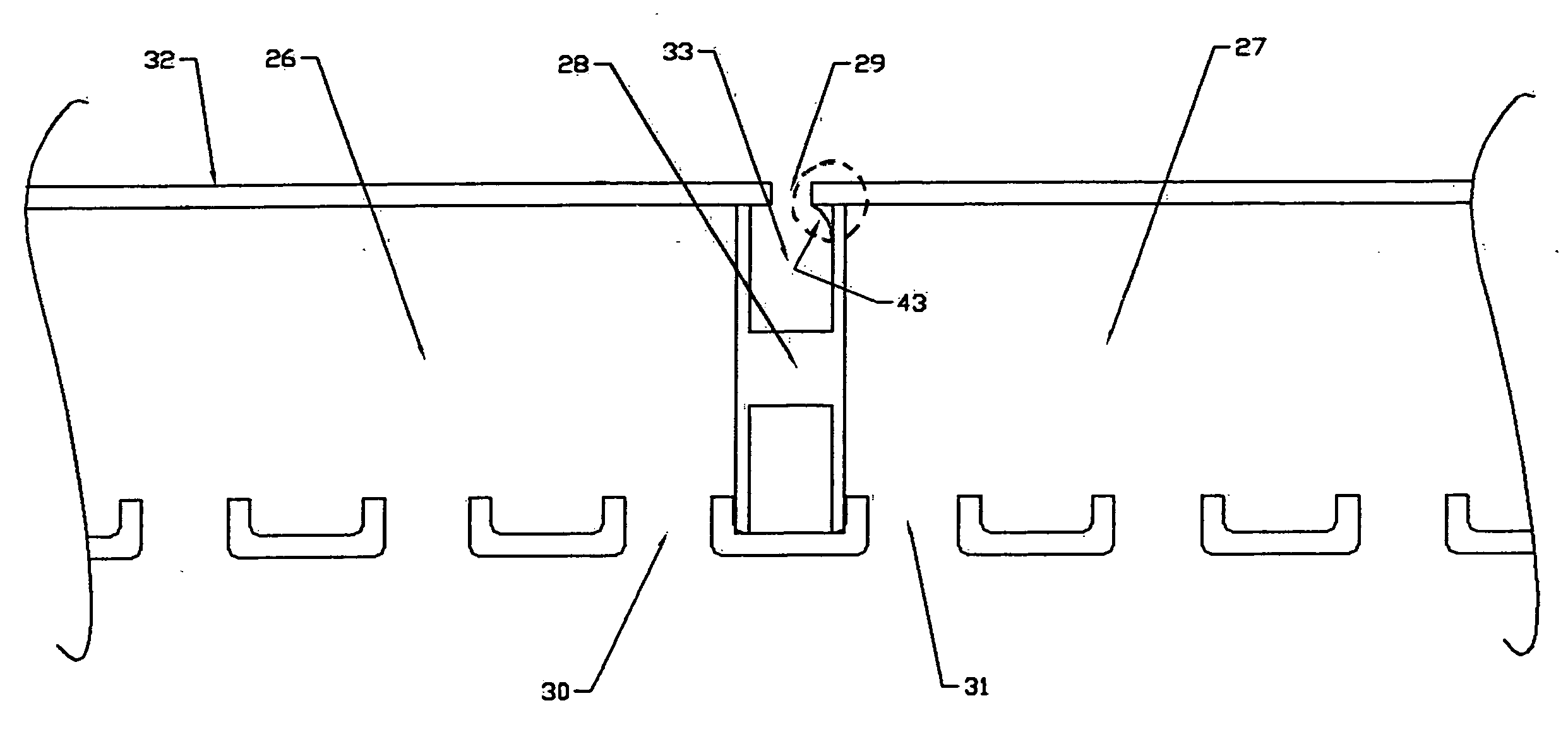
[0031] Generally, the present invention relates to a heat exchanger having a baffle system and to a method of forming the heat exchanger. The heat exchanger may be a single fluid or multi-fluid (e.g., 2, 3 or 4 fluid) heat exchanger. The heat exchanger may also be a single pass or multi-pass heat exchanger. Although the heat exchanger according to the present invention may be used for a variety of articles of manufacture (e.g., air conditioners, refrigerators or the like), the heat exchanger has been found particularly advantageous for use in automotive vehicles. For example, the heat exchanger may be used for heat transfer of one or more various fluids within a vehicle such as air or gasses, oil, transmission oil, power steering oil, radiator fluid, refrigerant, combinations thereof or the like. For example, in a highly preferred embodiment of the present invention there is contemplated a multi-fluid heat exchanger that includes an oil cooler or condenser in combination with an oil...


PUM


Abstract

There is disclosed a heat exchanger for transferring heat between at least two fluids and a method for forming the heat exchanger. The heat exchanger preferably includes one or more end tanks, one or more inlets and outlets, one or more tubes, one or more fins, and one or more improved baffle combinations including at least one single piece double baffle. The improved single piece double baffles act as part of a baffle system, with advantages over multiple-piece only double baffle systems due to being assembled in one piece.

Description

FIELD OF THE INVENTION [0001] The present invention relates generally to a heat exchanger and, more particularly, a multi-fluid heat exchanger, employing at least one single piece double baffle. BACKGROUND OF THE INVENTION [0002] In the automotive industry, in particular, it has become increasingly necessary to combine multiple functions in a single heat exchanger assembly. The need to reduce the number of overall components and to optimize assembly efficiency has driven the need for improved heat exchanger devices that combine increasingly efficient designs and multiple functions in packaging heretofore attainable using plural separate components or devices having inefficient designs. More specifically, there has been a growing need for an improved heat exchanger device, particularly for under the hood automotive vehicle applications, which combines multiple functions in a single assembly that is efficient to make and operate and that occupies substantially the same or less space t...

Claims


Application Information

Patent Timeline
IPC IPC(8): F28F9/00
CPCF28F2265/16F28F9/0212
Inventor LORENTZ, JAYSMITH, BRADLEY A.
Owner VALEO INC
Why Eureka
Try Eureka