
Flap interconnection system for aircraft

a technology of interconnection system and flap, which is applied in the field of flap interconnection system for aircraft, can solve the problems of insufficient space available, inability to bridge the maximum gap width of new designs, and inability to apply previously known interconnection system thickness of landing flap, etc., and achieves the effect of less space available and greater forces

Active Publication Date: 2006-02-02
AIRBUS OPERATIONS GMBH
View PDF14 Cites 17 Cited by
  • Summary
  • Abstract
  • Description
  • Claims
  • Application Information

AI Technical Summary

Benefits of technology

[0008] A further obstacle to the application of previously known interconnection systems is of the thickness of the landing flaps, i.e. their design height, due to the very slim flap batten (Klappenstrak), being considerably smaller in relation to the flap depth, so that at least in height there is considerably less space available for the interconnection systems. Another advantage of an interconnection system according to the present invention is that the interconnection system may be suitable for transferring significantly greater forces between adjacent flaps, even with very slim flap battens, than has been the case in known interconnection systems.

Problems solved by technology

For flap systems of newer aircraft, in particular large aircraft, an interconnection system that is only suitable for horizontal interconnection of flap systems may be inadequate.
Specifically, the maximum gap widths of new, larger designs are often too large to be able to be bridged by known interconnection and sealing systems.
A further obstacle to the application of previously known interconnection systems is of the thickness of the landing flaps, i.e. their design height, due to the very slim flap batten (Klappenstrak), being considerably smaller in relation to the flap depth, so that at least in height there is considerably less space available for the interconnection systems.

Method used


Image

  • Flap interconnection system for aircraft
  • Flap interconnection system for aircraft
  • Flap interconnection system for aircraft

Examples


Embodiment Construction

[0026] This detailed description and the drawings provide specific examples of the invention, but the invention should not be limited merely to the examples disclosed. Instead, the invention should be limited only by the claims that may eventually issue. Many variations in the system, changes in specific components of the system and uses of the system will be readily apparent to those familiar with the field based on the drawings and description provided.

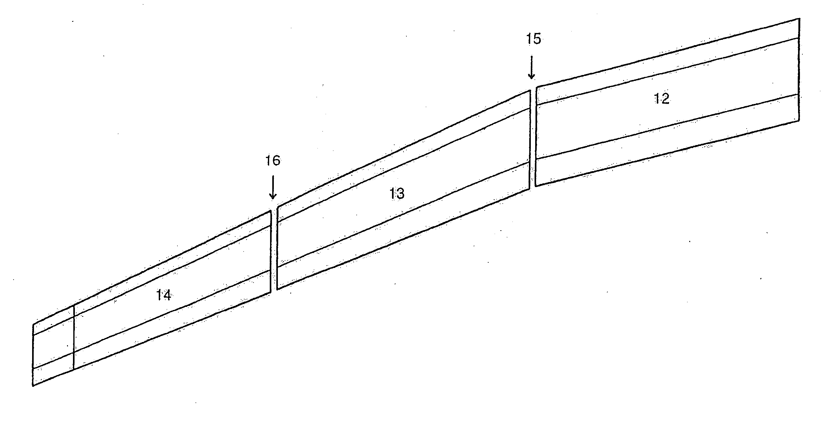
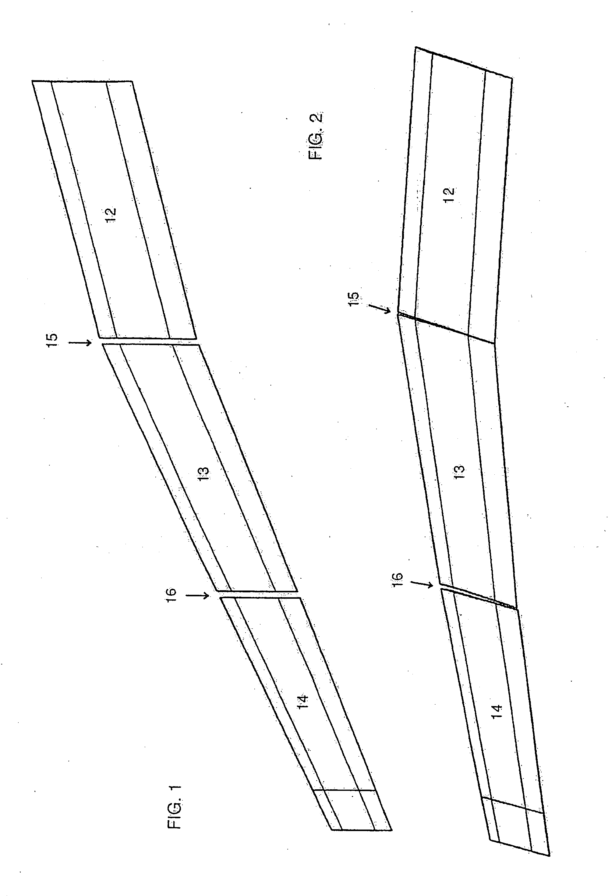
[0027]FIGS. 1 and 2 show three landing flaps 12, 13, 14 which extend side-by-side along an aircraft wing, generally speaking in the trailing edge region of said wing. In this arrangement, the first landing flap 13 is located on the side facing the fuselage, while the second and third landing flaps 13, 14 are adjacent in the direction of the wing tip.

[0028]FIG. 1 shows the relative position of these three landing flaps in their retracted positions (0 degree flap setting), while FIG. 2 shows their relative positions when they are ex...


PUM


Abstract

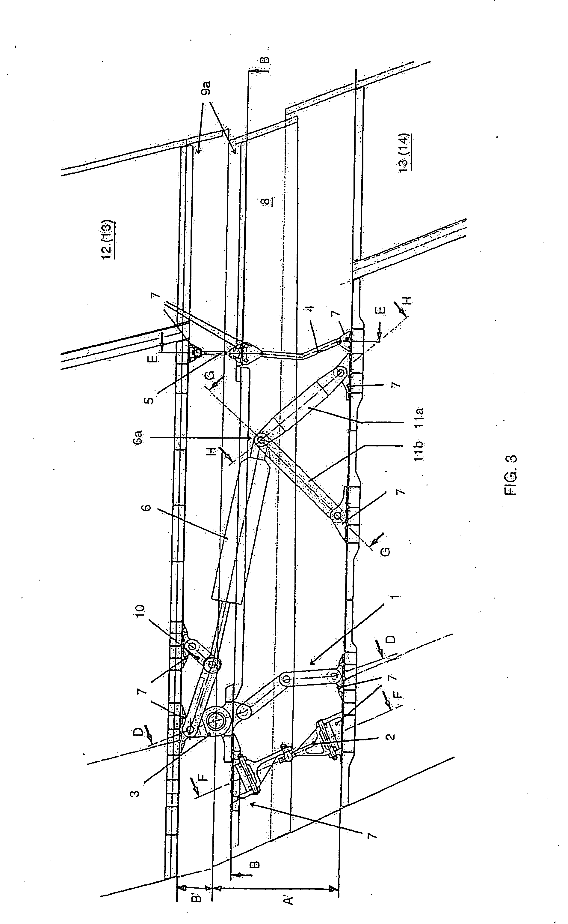
Described is an interconnection system, in particular for flaps which are located side-by-side, on an aircraft wing, for example landing flaps or high-lift flaps. The interconnection system is in particular characterised in that it comprises a correspondingly guided compensating profile for a gap between the flaps, which gap changes when the flaps are moved. Preferably, the interconnection system is combined with a failsafe device for adjacent flaps in the form of a longitudinally adjustable interconnection strut which is connected to the adjacent flaps by way of corresponding load introduction fittings. The interconnection system is in particular suitable for large aircraft in which the gap between adjacent flaps, due to the relatively large lateral movement of the flaps during retraction and extension, becomes relatively wide, and the forces acting on the flaps are relatively great.

Description

RELATED APPLICATIONS [0001] This application claims the benefit of the filing date of German Patent Application No. 10 2004 035 921.6 filed Jul. 23, 2004 to Poppe, et al., the disclosure of which is hereby incorporated herein by reference. FIELD OF THE INVENTION [0002] The field relates to aircraft flaps, for example, landing flaps or high-lift flaps, which are located side-by-side on the wing of an aircraft. BACKGROUND [0003] Generally speaking, flaps of this type are allocated to a separate drive system which can be activated by way of a common shaft, with which each of the flaps is driven or guided individually. To prevent uncontrolled movement of the respective flap in the case of a failure or fault in one of the drive systems, adjacent flaps are in each case interconnected by way of an interconnection system. [0004] Such an interconnection system which is used as a failsafe device (in horizontal direction of flight) is for example disclosed in DE 35 05 839 C2. In this system ad...

Claims


Application Information

Patent Timeline
Patent Type & Authority Applications(United States)
IPC IPC(8): B64C3/50
CPCB64C9/04B64C13/24B64C9/16
Inventor POPPE, BERNDAUHAGEN, KURT
Owner AIRBUS OPERATIONS GMBH
Learn More