Light emitting display

a technology of light-emitting displays and scan drivers, applied in the direction of instruments, static indicating devices, etc., can solve the problems of increasing power consumption and difficulty in getting high definition, and achieve the effects of reducing power consumption, reducing scan driver size, and reducing the size of pixel

Active Publication Date: 2006-02-02
SAMSUNG DISPLAY CO LTD
View PDF4 Cites 31 Cited by
  • Summary
  • Abstract
  • Description
  • Claims
  • Application Information

AI Technical Summary

Benefits of technology

[0019] An embodiment of the present invention provides a light emitting display and a scan driver, in which the size of a buffer is decreased, thereby decreasing the size of a scan driver to reduce power consumption in the light emitting display, and decreasing the size of a pixel to provide a high definition.

Problems solved by technology

Because of this, as the size of the scan driver 20 is increased, power consumption is increased.
In this case, it is difficult to get a high definition.

Method used


Image

  • Light emitting display
  • Light emitting display
  • Light emitting display

Examples


Embodiment Construction

[0031] In the following detailed description, exemplary embodiments of the present invention are shown and described, by way of illustration. As those skilled in the art would recognize, the described exemplary embodiments may be modified in various ways, all without departing from the spirit or scope of the present invention. Accordingly, the drawings and description are to be regarded as illustrative in nature, rather than restrictive.

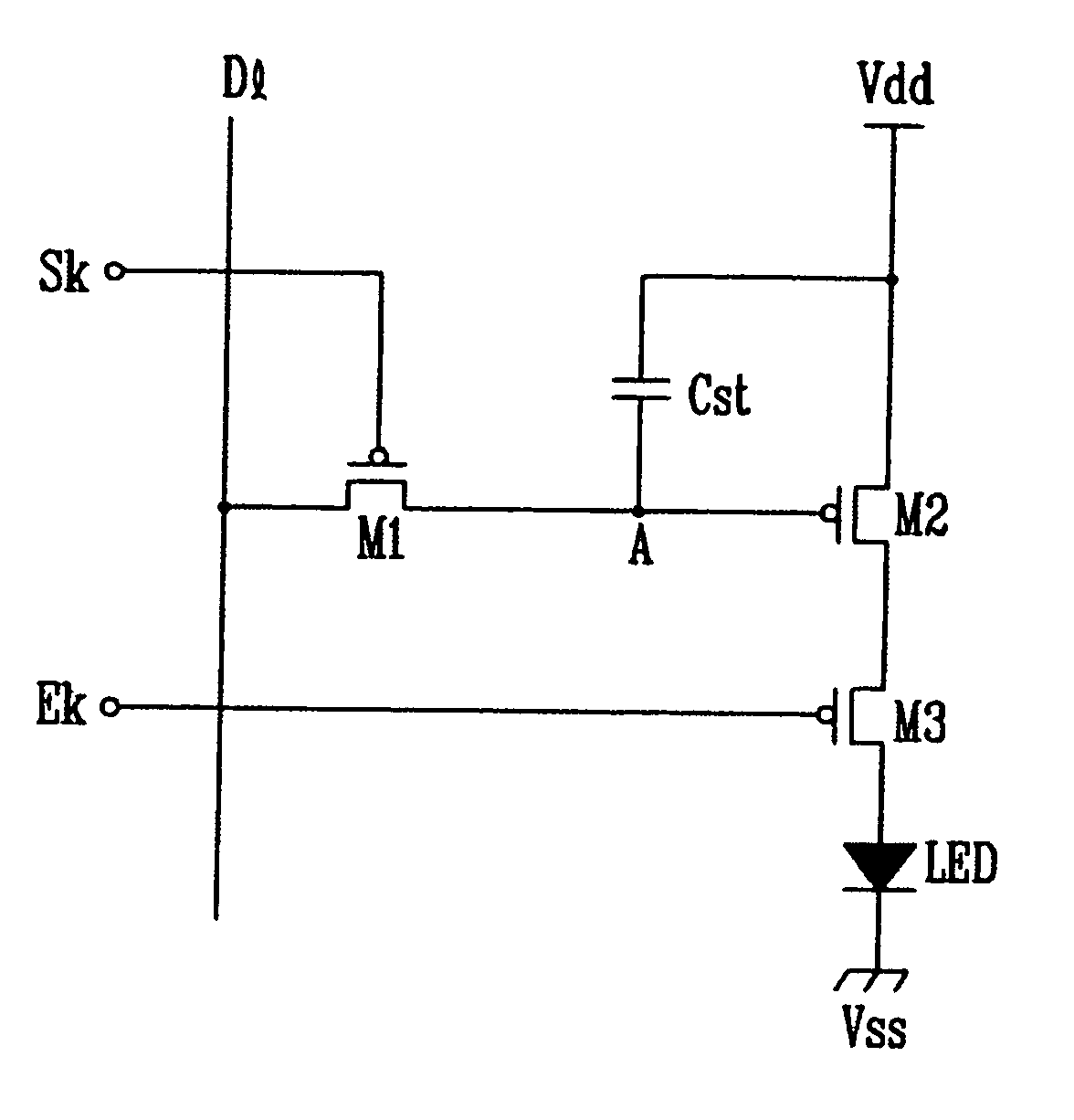
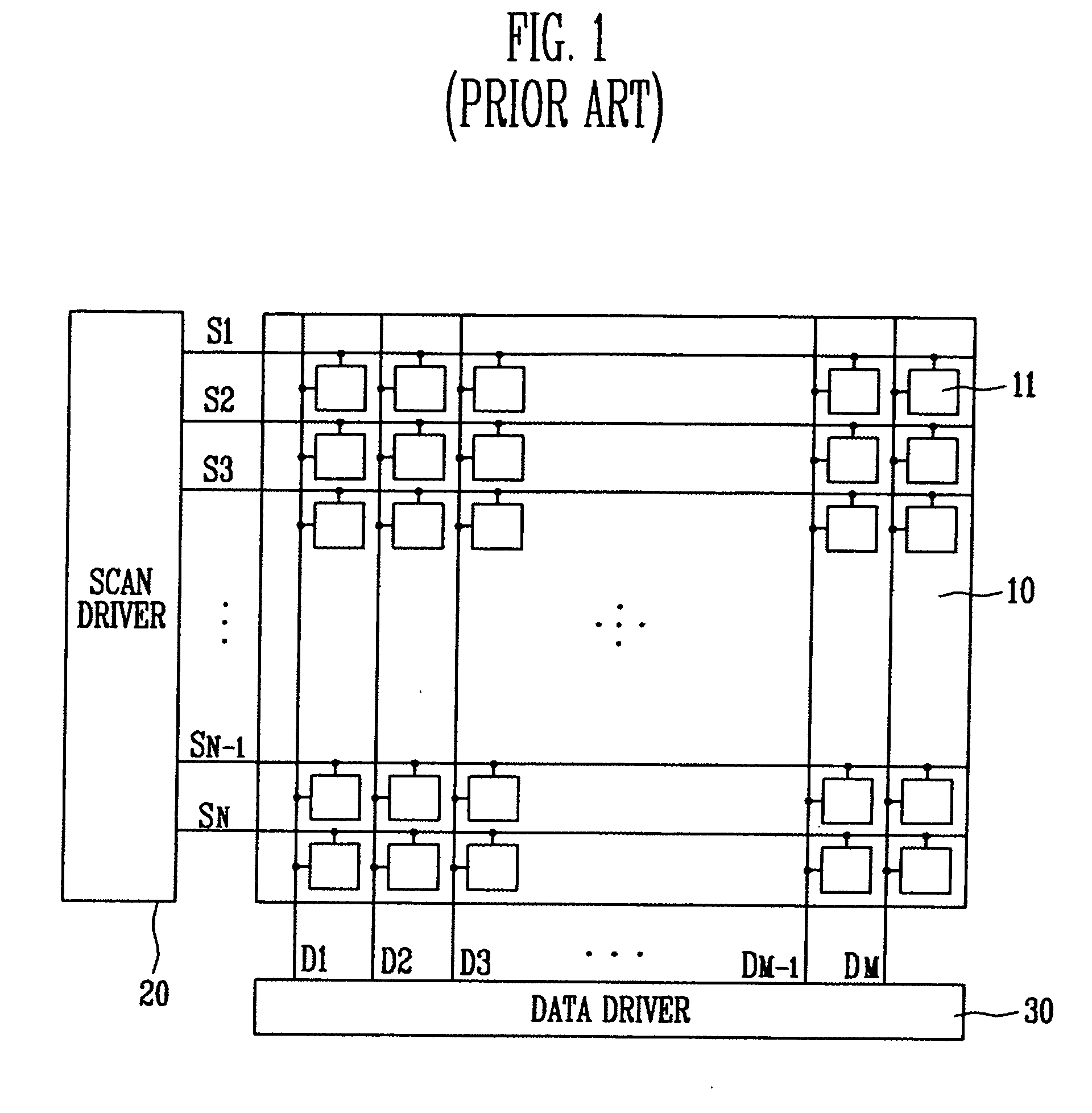
[0032]FIG. 3 is a plan view of a configuration of a light emitting display according to an embodiment of the present invention. As shown therein, the light emitting display according to the embodiment of the present invention includes a pixel area 100 having N×M pixels 110 and for displaying an image corresponding to light emissions of the pixels 110; a scan driver 200 for supplying scan signals and emission control signals to the pixel area 100; and a data driver 300 for supplying data signals to the pixel area 100.

[0033] The pixel area 100 includ...


PUM


Abstract

A light emitting display including a pixel area having a plurality of pixels, a scan driver for outputting a scan signal for selecting a predetermined pixel among the plurality of pixels of the pixel area, and an emission control signal for allowing a current to flow in the selected pixels. The scan driver includes: a signal generator adapted to generate the scan signal and the emission control signal; a first buffer adapted to transmit the scan signal to the pixel area; and a second buffer adapted to transmit the emission control signal to the pixel area. In the scan driver, the second buffer is smaller than the first buffer. The size of the second buffer is decreased to decrease the size of the scan driver, and/or to decrease the size of the predetermined pixel to get a high definition.

Description

CROSS-REFERENCE TO RELATED APPLICATIONS [0001] This application claims priority to and the benefit of Korean Patent Application No. 10-2004-0058904, filed on Jul. 27, 2004, in the Korean Intellectual Property Office, the entire disclosure of which is incorporated herein by reference. BACKGROUND [0002] 1. Field of the Invention [0003] The present invention relates to a light emitting display and a scan driver, and more particularly, to a light emitting display and a scan driver for outputting a scan signal and an emission control signal, in which the scan driver provided in the light emitting display includes a first buffer for outputting the emission control signal, the first buffer being smaller than a second buffer for outputting the scan signal, thereby decreasing the size of the scan driver. [0004] 2. Discussion of Related Art [0005] A thin and lightweight flat panel display has been widely used for monitors of various information terminals such as personal computers, mobile pho...

Claims


Application Information

Patent Timeline
Patent Type & Authority Applications(United States)
IPC IPC(8): G09G3/30
CPCG09G3/3233G09G3/3266G09G2330/021G09G2300/0842G09G2300/0861G09G3/3291G09G3/30
Inventor PARK, SUNG CHEONEOM, KI MYEONGPARK, YOUNG JONG
Owner SAMSUNG DISPLAY CO LTD
Why Eureka
Try Eureka