Device for optically viewing a stereoscopic observation beam path

a stereoscopic and beam path technology, applied in the field of optically viewing a stereoscopic observation beam path, can solve the problems of unavoidable vignetting, inability to correct astigmatism in the convergent beam path, and ergonomic disadvantages that are very significan

Inactive Publication Date: 2006-02-02
LEICA INSTR SINGAPORE PTE
View PDF20 Cites 26 Cited by
  • Summary
  • Abstract
  • Description
  • Claims
  • Application Information

AI Technical Summary

Benefits of technology

[0009] It is thus the object of the present invention to create an apparatus with which at least one stereoscopic observation beam path for an assi...

Problems solved by technology

The reason such microscopes have not proven successful on the market is because, as shown in FIG. 1 of this publication, the splitter prism is arranged beneath main objectives O1 and O2 of microscopes M1 and M2, and results there in an astigmatism in the convergent beam path that is not correctable because of the rotation of microscope M2 around M1.
It is disadvantageous in this context that the beam path is extremely long and thus results in further optically necessary corrective actions, for example for pupil location.
Combinations of deflection elements, as proposed in FIG. 2 through FIG. 7 of DE-AS 1 217 099, lead to unavoidable vignetting because of the long glass paths.
This results in ergonomic disadvantages that are very significant especially in the context of surgical mi...

Method used


Image

  • Device for optically viewing a stereoscopic observation beam path
  • Device for optically viewing a stereoscopic observation beam path
  • Device for optically viewing a stereoscopic observation beam path

Examples


Embodiment Construction

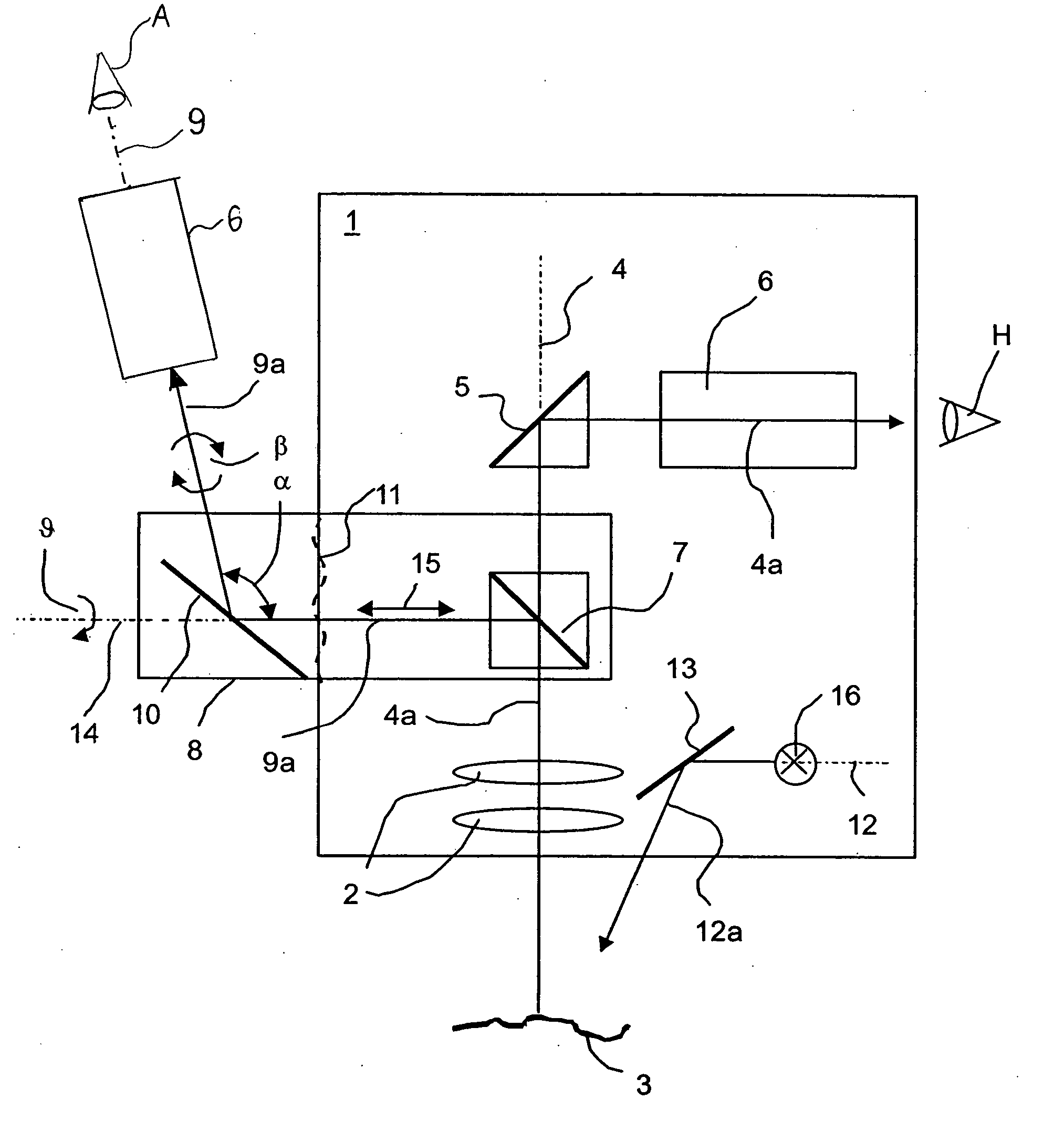
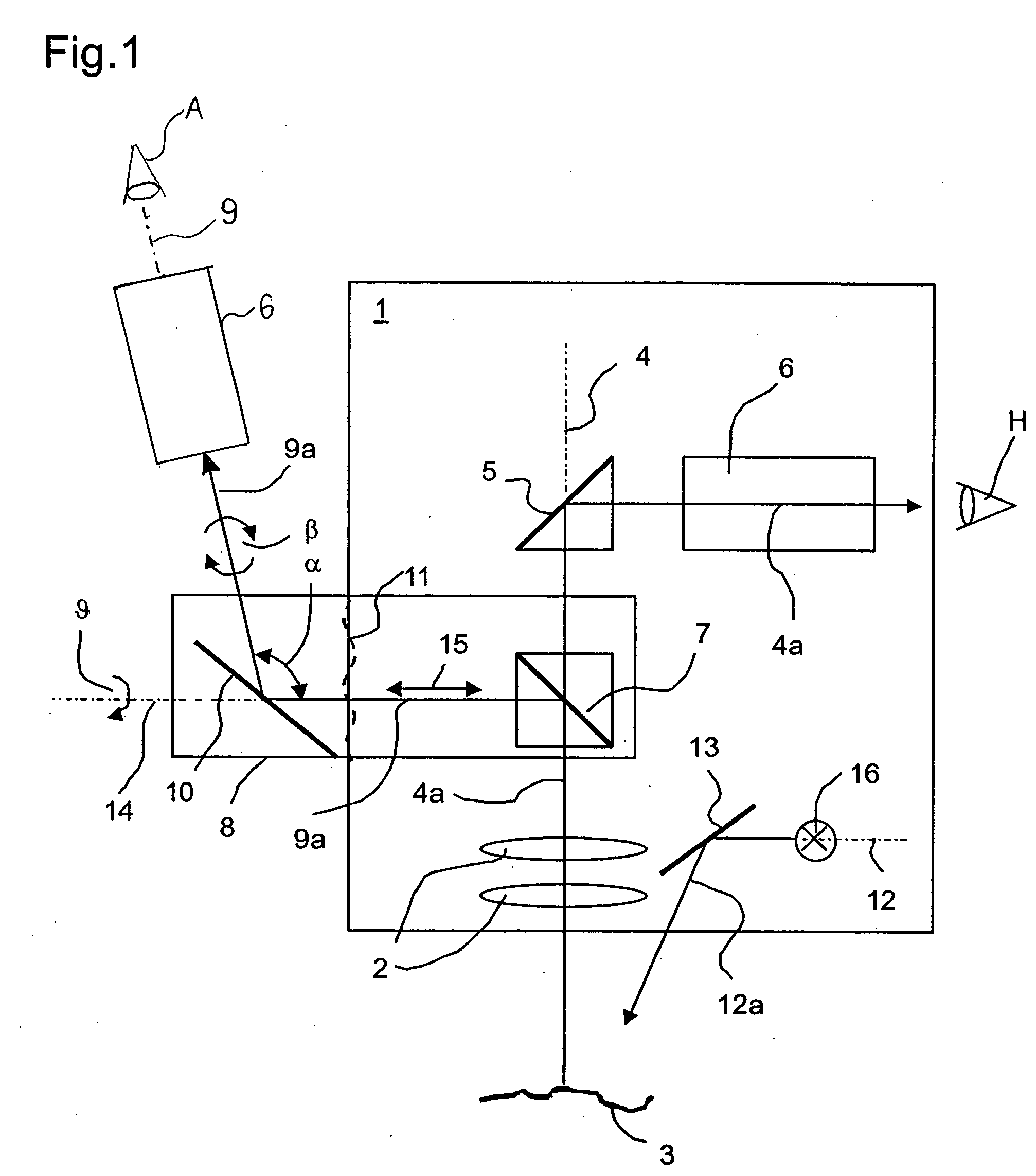
[0023]FIG. 1 depicts: a main microscope 1, with a surgeon as main observer H, having a main objective 2 with a vertical optical axis 4; an object 3; and an assistant's microscope 8 for an assistant A. An illumination beam path 12a having an axis 12, proceeding from a light source 16, is projected through a deflection element 13 onto an object 3 (e.g. a patient). Object 3 is imaged by way of stereoscopic main observation beam paths 4a, b, via a main objective 2, a beam splitter 7, and a further 5 deflection element 5, into a horizontally located zoom 6. Optionally, the main objective 2 may be arranged rotatably, together with the illumination system, for rotation about the optical axis 4 of the main objective 2.

[0024] As a consequence of the side view of main microscope 1, only one 4a of the two stereoscopic main observation beam paths 4a, b, one 9a of the two assistant's observation beam paths 9a, 9b, and one of the two zooms 6 of identical type, are visible in FIG. 1. The manner o...


PUM


Abstract

The invention concerns an apparatus for reflecting at least one stereoscopic observation beam path out of a main observation beam path of a microscope, for example a surgical stereomicroscope, having a zoom (6) whose axis is arranged at an angle to the optical axis (4) of the main objective (2), and having a beam splitter (7) for reflecting out stereoscopic assistant's observation beam paths (9a, b). The beam splitter (7) is arranged between the main objective (2) and the zoom (6), and is continuously rotatable, together with the assistant's microscope (8), about the optical axis (4) of the main objective (2), and is thus optically usable in any rotational position.

Description

CROSS-REFERENCE TO RELATED APPLICATIONS [0001] The present application is the U.S. National Stage of International Application No. PCT / EP2003 / 013493 filed Dec. 1, 2003, which claims priority of German Application No. 102 55 967.8 filed Nov. 29, 2002. FIELD OF THE INVENTION [0002] The invention concerns an apparatus or device for reflecting at least one stereoscopic observation beam path out of a microscope, for example a surgical stereomicroscope. BACKGROUND OF THE INVENTION [0003] In neurosurgery and ophthalmology, it is desirable for two equally qualified operators (surgeon and assistant) to be able to follow surgical occurrences under the microscope. From a very early date, numerous possibilities have already been offered for combining two microscopes with one another: [0004] German Examined Application DE-AS 1 217 099 discloses, in a number of variants, a stereomicroscopic device which comprises at least two stereomicroscopes M1 and M2 having a shared object plane, and which per...

Claims


Application Information

Patent Timeline
IPC IPC(8): G02B21/22G02B21/00
CPCG02B21/22G02B21/0012
Inventor SANDER, ULRICH
Owner LEICA INSTR SINGAPORE PTE
Why Eureka
Try Eureka