
Versatile low power driver for gigabit ethernet systems

a low-power, gigabit ethernet technology, applied in the field of digital voice and data communication, can solve the problems of limiting the number of ports that can be integrated on a single device, increasing without achieving significant performance gains, so as to reduce the power consumption of the line driver, reduce the inefficient transmit power consumption, and reduce the effect of phy power consumption

Inactive Publication Date: 2006-02-02
TEXAS INSTR INC
View PDF5 Cites 12 Cited by
  • Summary
  • Abstract
  • Description
  • Claims
  • Application Information

AI Technical Summary

Benefits of technology

[0009] The present invention provides a versatile power backoff system, comprising various constructs and methods, for reduce inefficient transmit power consumption in advanced Ethernet technologies—such as Gigabit Ethernet—and other similar technologies. Embodiments of the present invention provide a reduced power consumption line driver, which reduces PHY power consumption. The system of the present invention is readily implemented in a number of operational and physical embodiments, providing efficient and cost-effective optimization of a communication system's performance.
[0010] Specifically, the present invention provides a low-power transmitter mode system—a transmit power back-off scheme for 10 / 100 / 1000Base-T applications. This scheme significantly reduces the transmit (Tx) output swing for short transmission distances, and uses a high voltage swing for long transmission distances. In a short transmission distance, Tx swing is low (<<1 Volt), and Rx voltage is high (>>1 Volt). In a long cable case, just the opposite is true. The system of the present invention decreases, relatively, draw on central tap voltage or analog supply voltage—providing a reduced power-consumption line driver.

Problems solved by technology

A GE core typically consumes power from a chip's voltage supply (digital and analog) and, in specific implementations, may consume additional power from a central tap of an external transformer.
However, on-chip power consumption constraints usually limit the number of ports that can be integrated on single device.
Such scenarios generally increase line driver power consumption, without achieving a significant performance gain.

Method used


Image

  • Versatile low power driver for gigabit ethernet systems
  • Versatile low power driver for gigabit ethernet systems

Examples


Embodiment Construction

[0015] While the making and using of various embodiments of the present invention are discussed in detail below, it should be appreciated that the present invention provides many applicable inventive concepts, which can be embodied in a wide variety of specific contexts. The present invention is hereafter illustratively described primarily in conjunction with the design and operation of a certain high-performance Ethernet systems—particularly Gigabit Ethernet (GE) systems. Certain aspects of the present invention are further detailed in relation to specific operational modes and standards. Although described in relation to such constructs and schemes, the teachings and embodiments of the present invention may be beneficially implemented with a variety of digital communications technologies. The specific embodiments discussed herein are, therefore, merely demonstrative of specific ways to make and use the invention and do not limit the scope of the invention.

[0016] The present inven...


PUM


Abstract

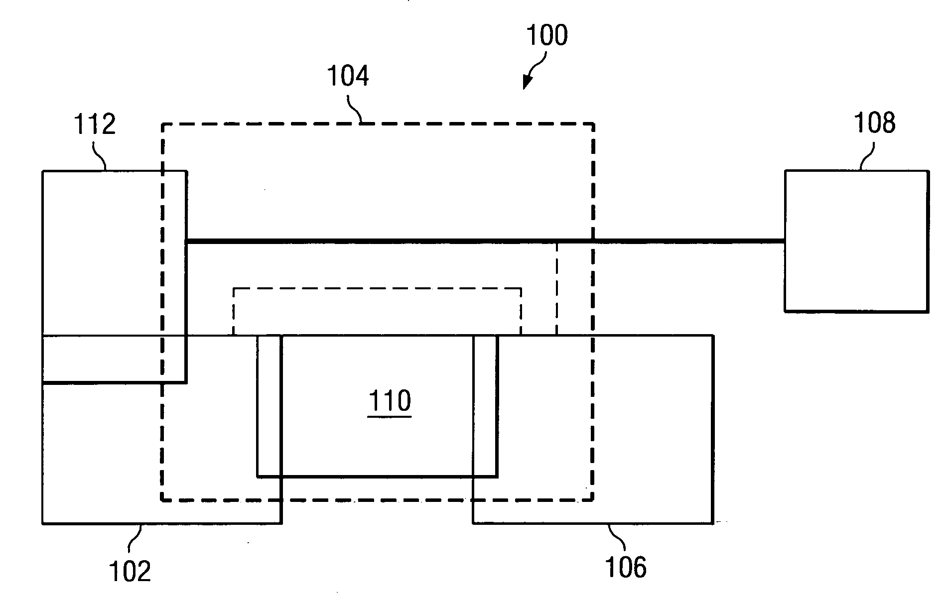
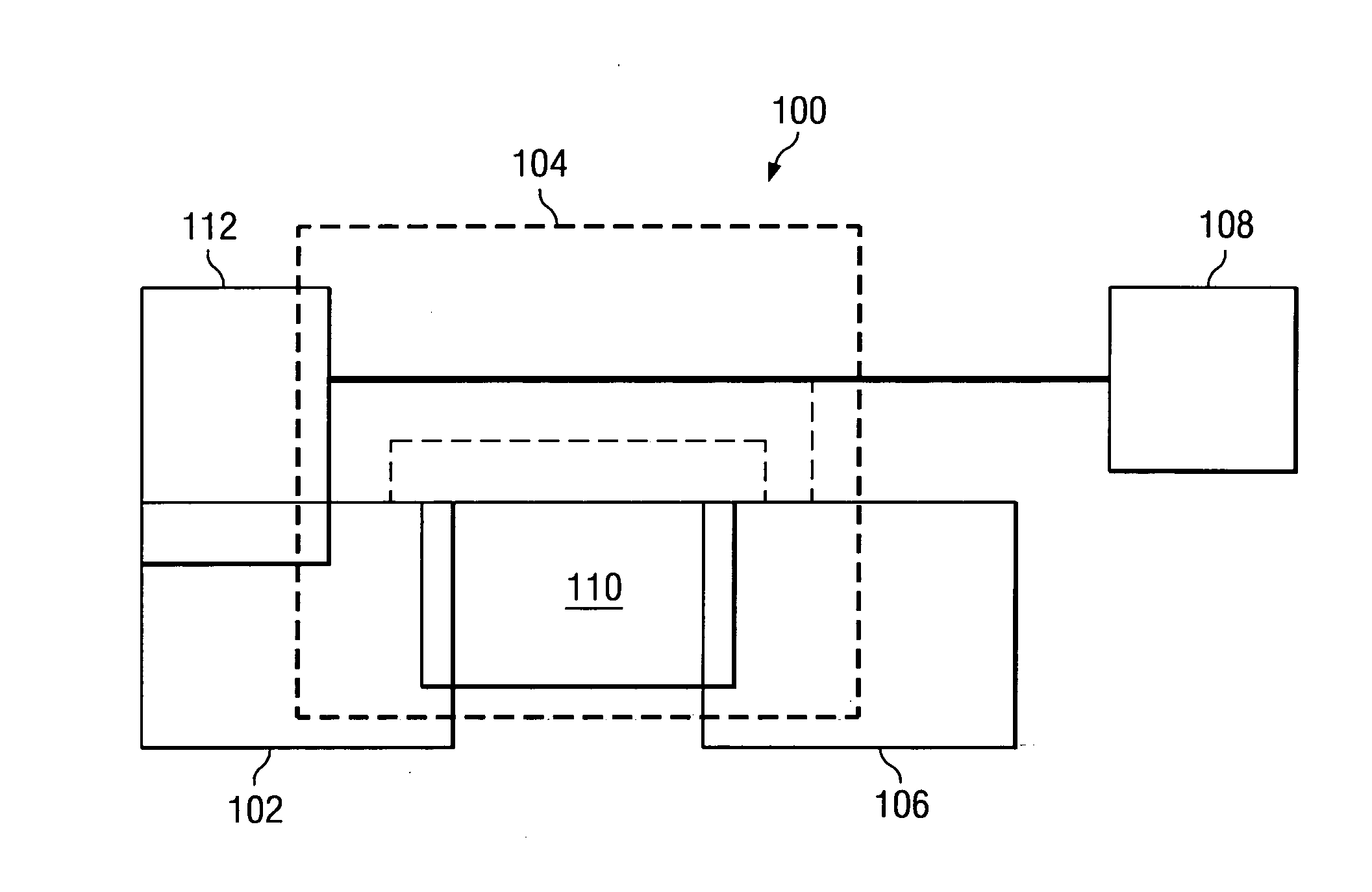
The present invention provides a system for optimizing transmission output power for a Gigabit Ethernet communications system (100). A PHY operational layer (104) is provided, with a backoff construct (102) that is at least partially implemented within the PHY operational layer. A second end component (108) is communicatively coupled to the PHY operational layer. An estimating construct (110) is implemented within the PHY operational layer, and is cooperatively associated with the backoff construct. The estimating construct determines whether the second end component is at a short or a long distance and, responsive to that determination, the backoff construct adjusts transmit output voltage swing.

Description

PRIORITY CLAIM [0001] This application claims priority of U.S. Provisional Application No. 60 / 592,304, filed Jul. 28, 2004.TECHNICAL FIELD OF THE INVENTION [0002] The present invention relates generally to the field of digital voice and data communications and, more particularly, to a versatile, low-power line driver system for Gigabit Ethernet applications. BACKGROUND OF THE INVENTION [0003] Among digital communication technologies, Ethernet has been a popular networking protocol for a number of years. Over those years, efforts have been made to advance Ethernet performance. For example, Fast Ethernet increased Ethernet speed from 10 to 100 megabits per second (Mbps). More recently, Gigabit Ethernet (GE) builds on top of the Ethernet protocol—increasing speed tenfold over Fast Ethernet to 1000 Mbps, or 1 gigabit per second (Gbps). Ethernet-based protocols are prevalent throughout a wide variety of high-speed local area network backbones and server systems. [0004] In order to accele...

Claims


Application Information

Patent Timeline
Patent Type & Authority Applications(United States)
IPC IPC(8): H04L12/413H04L12/66
CPCH04L12/10
Inventor SASSON, NIR
Owner TEXAS INSTR INC
Learn More