Axial flow steam turbine assembly

a technology of axial flow steam turbines and assembly parts, which is applied in the direction of machines/engines, stators, liquid fuel engines, etc., to achieve the effect of greater thermal inertia and greater stiffness

Active Publication Date: 2006-02-02
GENERAL ELECTRIC TECH GMBH
View PDF4 Cites 6 Cited by
  • Summary
  • Abstract
  • Description
  • Claims
  • Application Information

AI Technical Summary

Benefits of technology

[0012] the other of the first and second turbines comprises at least one turbine stage—referred to as a modified turbine stage—having an annular row of static blades, which extend between an outer static ring and an inner static ring, and an annular row of moving blades, and a rotor drum having peripherally extending slots in which root portions of the moving blades are held, a sealing device acting between the inner static ring and the rotor drum, the outer static ring being axially located in a recess in a turbine casing, and the outer static ring having greater thermal inertia and greater stiffness than the inner static ring and being capable of limited radial movement relative to the turbine casing.

Problems solved by technology

A disadvantage of this arrangement is that the outer shroud portions 31 move with the casing 28 as it expands and contracts.

Method used


Image

  • Axial flow steam turbine assembly
  • Axial flow steam turbine assembly
  • Axial flow steam turbine assembly

Examples


embodiment 1

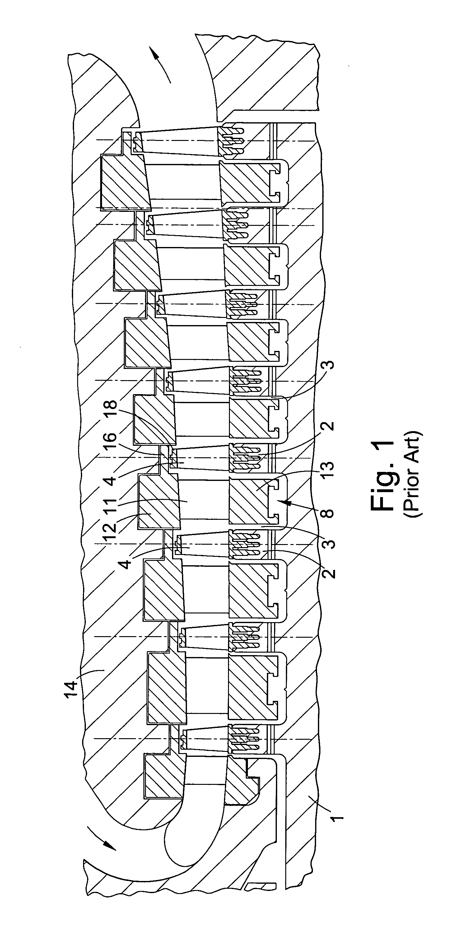
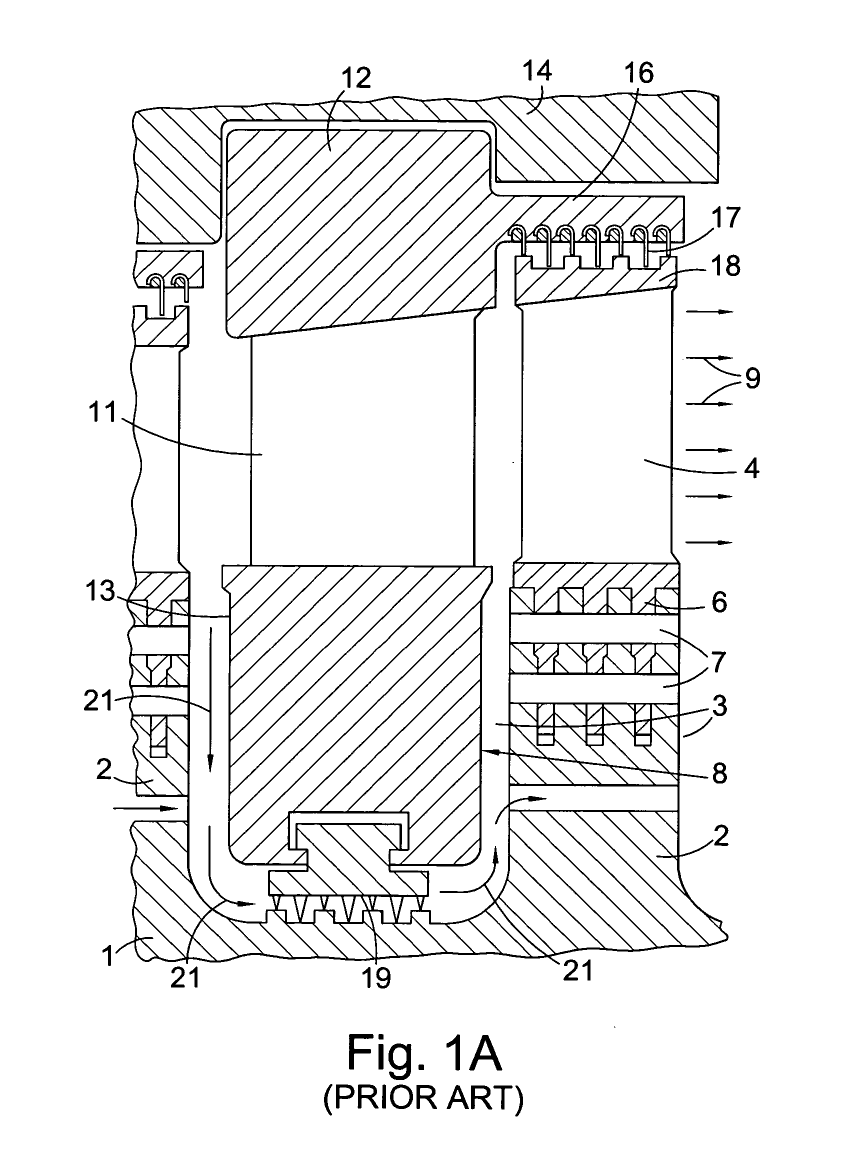
[0057] Referring to FIG. 6, the first exemplary embodiment comprises an HP steam turbine 100 having a conventional disc / diaphragm with impulse turbine stages, as described above with reference to FIG. 1, and an IP steam turbine 101 having a drum-type structure with modified turbine stages, as described with reference to FIG. 7.

[0058] An advantage is that an existing turbine assembly with an IP turbine of conventional disc / diaphragm construction can be modified by replacing the conventional impulse-type blading with the modified blading and using a drum-type rotor. The modified turbine stages, with cross-key location, give enhanced maintenance of circularity. The modification is not too radical or inconvenient and may allow re-use of the IP turbine casing.

[0059] Any suitable type of LP steam turbine may be used or the LP turbine 102, in particular any of the LP turbines described with reference to FIGS. 10 to 12.

embodiment 2

[0060] The second exemplary embodiment is the same as Embodiment 1 except that the IP steam turbine 101 has a drum-type structure with modified turbine stages and reaction turbine stages, as described with reference to FIG. 8. This has the advantage of lower cost, the casing-mounted static blades of the reaction turbine stages being cheaper.

embodiment 3

[0061] The third exemplary embodiment comprises an IP steam turbine 101 having a conventional disc / diaphragm structure with impulse turbine stages, as described above with reference to FIG. 1, and an LP steam turbine 102 having a drum-type structure with modified turbine stages, as described with reference to FIG. 10.

[0062] The advantage of this arrangement is similar to that mentioned in connection with Embodiment 1.

[0063] Any suitable type of HP steam turbine may be used as the HP turbine 100, in particular any of the HP turbines described with reference to FIGS. 1, 2, 7, 8, and 9.


PUM


Abstract

One turbine, e.g. a high pressure (HP) turbine, has a conventional diaphragm and disc structure with impulse turbine stages. A preceding or following turbine, e.g. an intermediate (IP) turbine, on a common axis and on the same steam path, has a rotor drum which carries an annular row of moving blades having root portions held within a slot in the periphery of the drum. A turbine casing surrounds the drum and carries a static blade assembly with an annular row of static blades which, together with the annular row of moving blades, constitutes a modified turbine stage. The static blade assembly has a radially inner static ring with a radially inner side confronting the periphery of the drum. A seal acts between the inner static ring and the rotor. The static blade assembly has an outer static ring which has a substantially greater thermal inertia and stiffness then the inner static ring and which is capable of sufficient sliding relative to the casing in a radial sense to accommodate relative thermal expansion and contraction of the outer static ring and the turbine casing.

Description

[0001] Priority is claimed to United Kingdom Patent Application No. GB 0416932.2, filed Jul. 29, 2004, the entire disclosure of which is incorporated by reference herein. [0002] The present invention relates to axial flow steam turbine assemblies that include at least two turbines. BACKGROUND [0003] Steam is supplied to a turbine at high pressure and temperature from a boiler and the energy in the steam is converted into mechanical work by expansion through the turbine. The expansion of the steam takes place through a series of static blades or nozzles and moving blades. An annular row of static blades or nozzles and its associated annular row of moving blades is referred to as a turbine stage. After the steam has been expanded in a high pressure (HP) turbine, it is conventional to return it to the boiler for re-heating and then to return the steam to an intermediate pressure (IP) turbine, from which the steam exhausts through one or more low pressure (LP) turbines. Usually the turb...

Claims


Application Information

Patent Timeline
Patent Type & Authority Applications(United States)
IPC IPC(8): F01D11/00F01D11/18
CPCF05D2300/502F01D11/18
Inventor BLATCHFORD, DAVID PAULHEMSLEY, PHILIP DAVID
Owner GENERAL ELECTRIC TECH GMBH
Why Eureka
Try Eureka