Method of marking a skin for a vehicle interior panel

a technology for interior trim and skin, applied in the direction of electric/magnetic/electromagnetic heating, vehicular safety arrangements, pedestrian/occupant safety arrangements, etc., can solve the problems of disproportionate production costs, expensive options, albeit expensive and environmentally challenging, etc., and achieve the effect of reducing contact, noise and wear

Inactive Publication Date: 2006-02-02
COLLINS & AIKMAN PROD CO
View PDF29 Cites 72 Cited by
  • Summary
  • Abstract
  • Description
  • Claims
  • Application Information

AI Technical Summary

Benefits of technology

[0020] Accordingly, the present invention provides a structure and a method for combining a flat wire with a three-layer instrument panel without the need for separate fasteners, such as screws, or adhesives.
[0034] According to another feature of the invention, the foam entering into the substrate aperture reduces contact, noise and wear between the flat wire and a surface of the substrate aperture.
[0035] According to another feature of the invention, the foam exiting from the substrate aperture surrounds at least a portion of the flat wire, prevents the flat wire from being displaced from an embedded position and reduces contact between the flat wire and a corner of the substrate aperture.

Problems solved by technology

Continuing, the '429 patent recites that such a prior art three-layer instrument panel, however, is not satisfactory because the base and the padding have to be produced independently of each other and then bonded together, resulting in a disproportionate production cost.
However, when the base is formed from a foamed resin, the '429 patent then discloses that the FPC and couplers may not be mounted with screws or adhesives.
Currently, there are numerous means to accomplish this end, albeit expensive and environmentally challenging.
Unfortunately, it is an expensive option as it adds labor, material, cycle time (to dry), energy costs and waste management / environmental issues (overspray, emissions, disposal).
Alternatively, hot stamping, in which a roll leaf is stamped with heated metal dies onto a plastic surface, can provide a multi-colored image, however it is not useful on a flexible surface and uses expensive tooling (printing plate) and equipment.
Similar to the previous referenced painting process, there are environmental disadvantages due to the use of solvents.
In addition, there are numerous steps and time added to the manufacturing process and, there is always a possibility of the coating being worn through during the useful life of the component.

Method used


Image

  • Method of marking a skin for a vehicle interior panel
  • Method of marking a skin for a vehicle interior panel
  • Method of marking a skin for a vehicle interior panel

Examples


Embodiment Construction

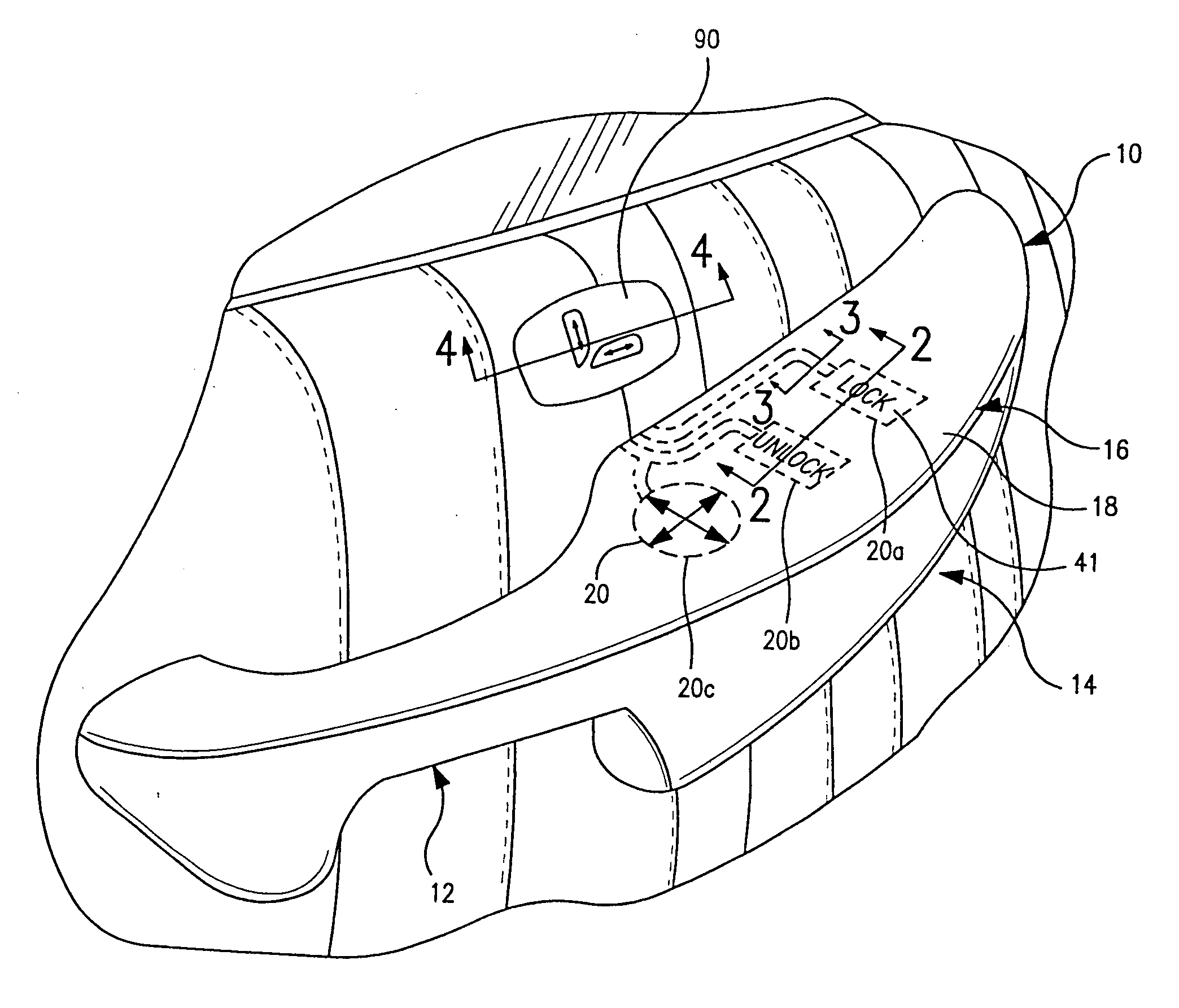
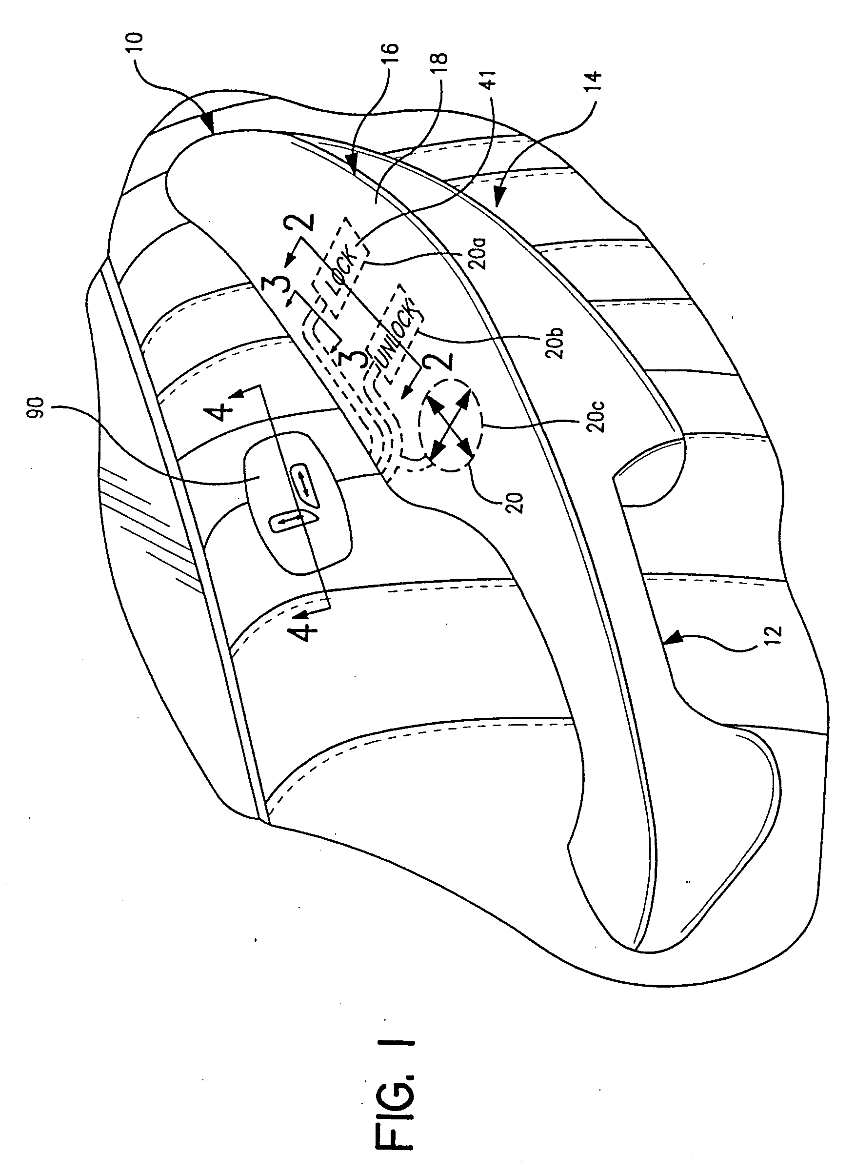
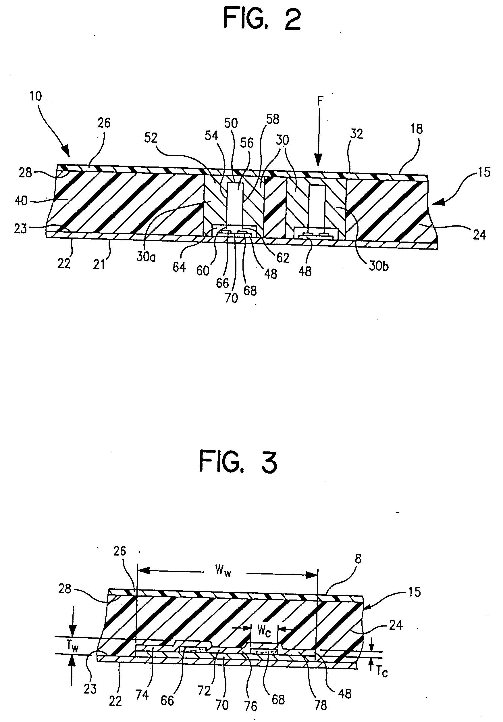
[0060] An exemplary vehicle interior trim panel electrical switch assembly of the type for actuating various vehicle electrical devices is shown at 10 in FIG. 1 in connection with an armrest 12 for a vehicle trim panel 14, such as a door panel. As shown in FIGS. 1 and 2, the armrest 12 is formed as a soft feel composite 15 which includes a switch panel portion 16 that has an outer surface 18 covering a switch array 20 including three electrical switches indicated at 20a-20c. Two of the three electrical switches may be for locking and unlocking the doors of the vehicle while the remaining switch may be a multiposition switch for adjusting the position of the side view mirror. Other switches not shown may include, but are not limited to, switches for opening and closing windows, seat adjustment and for selecting either the left or the right side view mirror for adjustment.

[0061] The armrest 12 is shown as a separate member from the trim panel 14, but the armrest and trim panel 14 cou...


PUM

PropertyMeasurementUnit
densityaaaaaaaaaa
elongationaaaaaaaaaa
densityaaaaaaaaaa

Abstract

A method of marking a skin for a vehicle interior trim panel comprising providing a skin with a color and an outer surface. A laser is applied to the outer surface such that a portion of the skin surface contacted by the laser changes color relative to a portion of the outer skin not contacted by the laser to create a marking in the outer skin surface indicating the presence of a vehicle component or function. In particular, an image, pattern, or color contrast may be created on the skin. A unique hole pattern and size distribution caused by the laser may provide a skin with a woven fabric texture. In addition, stitches formed on a skin surface may be colored differently from the surrounding skin surface to distinguish their appearance.

Description

CROSS-REFERENCE TO RELATED APPLICATIONS [0001] This application is a continuation-in-part of U.S. patent application Ser. No. 0 / 033,437, filed Dec. 28, 2001, which is a divisional application of U.S. patent application Ser. No. 09 / 625,117, filed Jul. 25, 2000.TECHNICAL FIELD OF THE INVENTION [0002] This invention relates generally to the method of marking a skin for a vehicle interior trim panel. More particularly, this invention relates to surface decoration of automotive trim components, in particular using a laser to create an image, pattern or color contrast. The decoration may be merely a color change in the area irradiated by the laser or may be an engraving into the surface due to melting or ablation of the polymer, or a combination of both. More specifically, the present invention relates to the laser treatment of a cast plastic surface with a unique hole pattern and size distribution to provide the appearance of woven fabric texture. In addition, stitches and accent lines f...

Claims


Application Information

Patent Timeline
Patent Type & Authority Applications(United States)
IPC IPC(8): B32B3/10
CPCB29C49/00B29C51/10B29C2791/006B41M5/24B44C1/005B44C1/228Y10T428/24612B60R13/005B60R13/02B60R13/0237B60R21/2165B60R2013/0287Y10T428/24322B60R13/00
Inventor LELAND, RICHARDGRAY, JOHN D.
Owner COLLINS & AIKMAN PROD CO
Why Eureka
Try Eureka