
WLAN access point with extended coverage area

a wireless communication and access point technology, applied in substation equipment, electrical equipment, network topologies, etc., can solve the problems of consuming no consuming capacity otherwise available for payload data communication, etc., to reduce link quality, reduce bit rate, and consume capacity

Active Publication Date: 2006-02-02
HONG KONG APPLIED SCI & TECH RES INST
View PDF10 Cites 124 Cited by
  • Summary
  • Abstract
  • Description
  • Claims
  • Application Information

AI Technical Summary

Benefits of technology

[0011] Embodiments of the invention implement the foregoing multi-beam antenna technology with little or no hardware modifications to AP circuitry, except that directly associated with the antenna and associated signal feed matrix. Such embodiments may implement software modifications and / or hardware modifications to access point (AP) circuitry in order to implement optimal beam determinations, to implement time division protocols, and / or the like. The foregoing optimal beam determinations and time division protocols may result in introducing additional overhead into the communication protocols, thereby consuming capacity otherwise available for payload data communication. However, as communication protocols, such as those set forth in the IEEE 802.11 standards, useful with embodiments of the present invention provide for decreased bit rates as link quality decreases, use of multi-beam antenna technology according to such embodiments is expected to provide improved link quality and, therefore, may provide a net increase in payload data capacity.

Problems solved by technology

The foregoing optimal beam determinations and time division protocols may result in introducing additional overhead into the communication protocols, thereby consuming capacity otherwise available for payload data communication.
Such embodiments may implement hardware modifications without introducing additional overhead into the communication protocols, and thus consuming no capacity otherwise available for payload data communication.

Method used


Image

  • WLAN access point with extended coverage area
  • WLAN access point with extended coverage area
  • WLAN access point with extended coverage area

Examples


Embodiment Construction

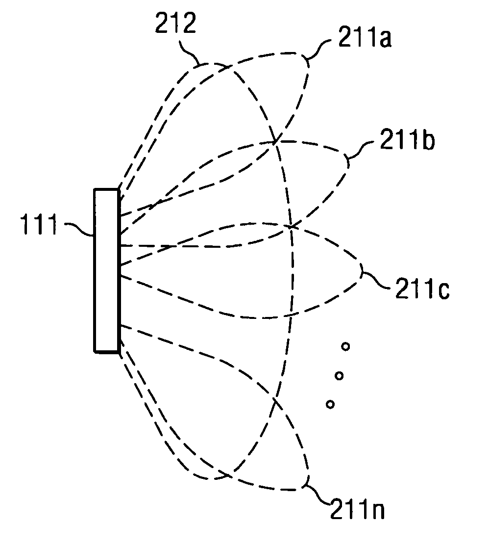
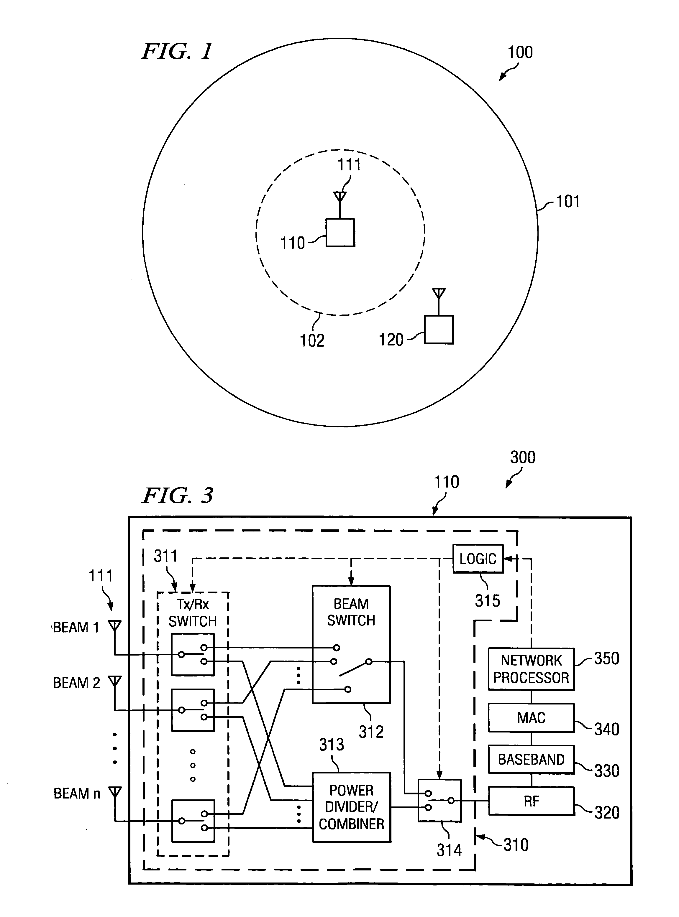
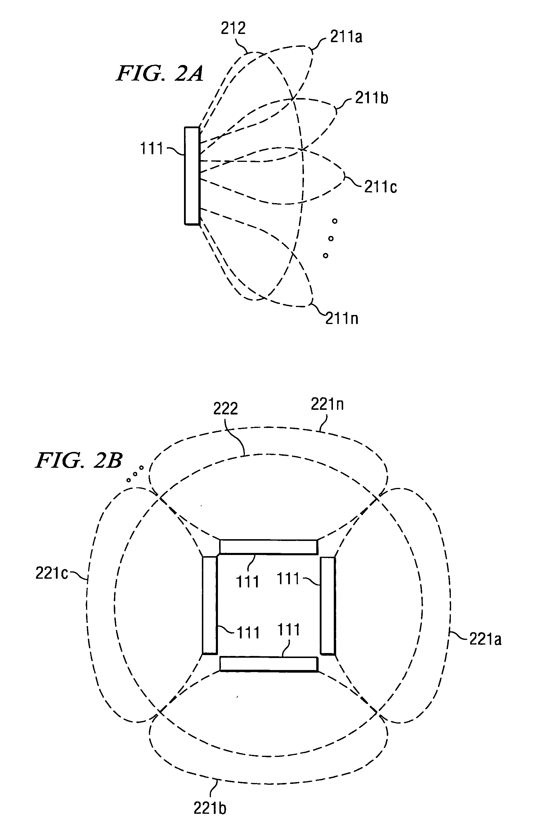
[0029] Embodiments of the present invention provide high bandwidth data communication within a large coverage area using multi-beam antenna technology. For example, a larger or extended WLAN coverage area may be provided according to the present invention using a controllable multi-beam configuration. In operation according to such an embodiment, a station disposed anywhere within the coverage area of the WLAN infrastructure operable according to embodiments of the present invention may operate in a substantially conventional manner to communicate with an access point (AP), thereby being provided high data rate links. High bit rate data, such as may carry payload data, may then be transmitted through one or more directional antenna beams of the multi-beam antenna system targeted at the appropriate stations. Multicast transmissions, simultaneously using a plurality of the antenna beams of the multi-beam antenna system to transmit a signal, may be used to provide control or overhead d...


PUM


Abstract

Disclosed are systems and methods which provide high bandwidth data communication with respect to a large coverage area using smart antenna and / or directional antenna (referred to herein as multi-beam antenna) technology. Circuitry may be provided at a WLAN AP to provide selection of particular antenna beams used in the downlink and / or uplink, control of multicast transmission, control of unicast transmission, and to provide antenna pattern shaping techniques. Embodiments implement multi-beam antenna technology with little or no hardware modifications to AP circuitry. Other embodiments implement multi-beam technology using radio front-end and / or radio hardware modifications to AP circuitry. Various diversity techniques may be implemented, such as selection diversity, maximum ratio combining, and equal gain combing. To provide desired antenna pattern shaping, phase offsets with respect to a signal as transmitted in each antenna beam may be employed.

Description

CROSS-REFERENCE TO RELATED APPLICATIONS [0001] The present application is related to co-pending and commonly assigned U.S. patent application Ser. No. 10 / 833,626 entitle “Systems and Methods for Wireless Network Range Extension,” filed Apr. 28, 2004, the disclosure of which is incorporated herein by reference.TECHNICAL FIELD [0002] The present invention is related generally to wireless communications and, more particularly, to providing wireless communications with extended range. BACKGROUND OF THE INVENTION [0003] Wireless communication systems typically have a base station or access point from which radio signals are transmitted and propagate. These signals are then received by a mobile station, remote station, user station, client station, subscriber station, etcetera (referred to herein collectively as stations) allowing communication to proceed. Stations may be, for example, a computer with a wireless modem such as a notebook computer fitted with a wireless local area network (...

Claims


Application Information

Patent Timeline
IPC IPC(8): H04M1/00
CPCH04B7/0617H04B7/088H04W16/30H04W84/12H04B7/0695H04B7/0682H04B7/0691H04B7/082H04W88/08
Inventor TAO, MEIXIAWONG, CHEONG YUIWANG, YANLAU, KIN NANGMURCH, ROSS D.LIEW, SOUNG C.GEORGE, DOUGLAS R.
Owner HONG KONG APPLIED SCI & TECH RES INST
Learn More