
Large area position/proximity correction device with alarms using (D)GPS technology

a technology of large-area position/proximity correction and alarm, which is applied in the direction of electric signalling details, navigation instruments, instruments, etc., can solve the problems of limited spacial resolution for precise boundary discrimination, the expense of these systems, and the work involved in burying the wire loop

Inactive Publication Date: 2006-02-09
INT RES INST
View PDF99 Cites 89 Cited by
  • Summary
  • Abstract
  • Description
  • Claims
  • Application Information

AI Technical Summary

Benefits of technology

[0010] The present invention employs GPS signals. A GPS signal contains a pseudorandom code, ephemeris data and almanac data. The pseudorandom code is simply an I.D. code that identifies which satellite is transmitting information. Ephemeris data, which is constantly transmitted by each satellite, contains important information about the status of the

Problems solved by technology

Although these systems are not visible on the property and are less laborious to install than a standard post fence, there is still quite a lot of work involved in burying the wire loop.
However, the complexity and expense of these systems makes them undesirable.
Furthermore, the spacial resolution is limited for precise boundary discrimination.
Prior attempts to produce a GPS based containment system have had limited success, primarily because of their approach.
This solution can be costly and complicated.

Method used


Image

  • Large area position/proximity correction device with alarms using (D)GPS technology
  • Large area position/proximity correction device with alarms using (D)GPS technology
  • Large area position/proximity correction device with alarms using (D)GPS technology

Examples


examples

[0061] % Cn—Enable / Disable Data Compression

[0062] % En—Auto-Retrain control

[0063]&Cn—DCD Control

[0064]&Dn—DTR Option

[0065]&Fn—Recall Factory Profile

[0066] Referring to FIG. 5, a perspective view of a base / mobile station 16 is illustrated. Base / mobile station 16 contains a readout screen 19, a communications antenna 17 and all the necessary hardware to communicate with collar 1 (not shown). Readout screen 19 can be an LCD in order to read and map the coordinates when the collar is polled and for any diagnostics needed on the base station. Station 16 can be a stand-alone unit or a wireless phone with location capabilities and of the new 3-G design. The capability to reprogram individual collars in the field and manage a heard is built into the station. However, each collar can communicate with other collars eliminating the need for exterior management. In one embodiment, the base station can be used as a differential station whereby it would include a GPS module 106 (not shown). ...


PUM


Abstract

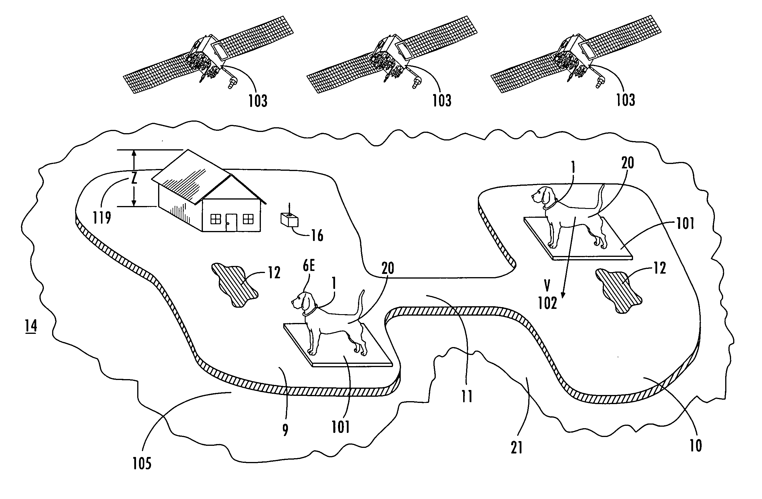
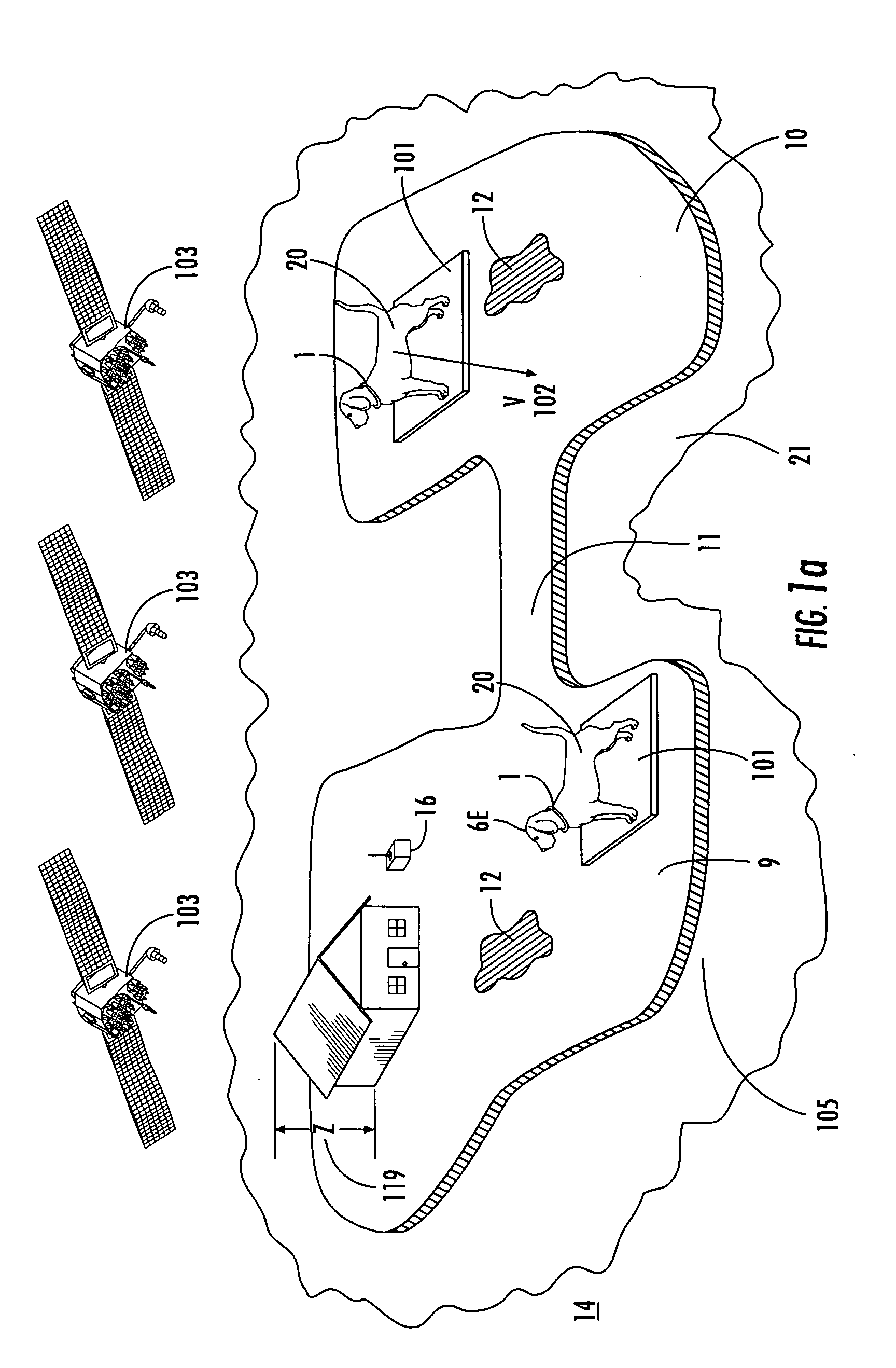
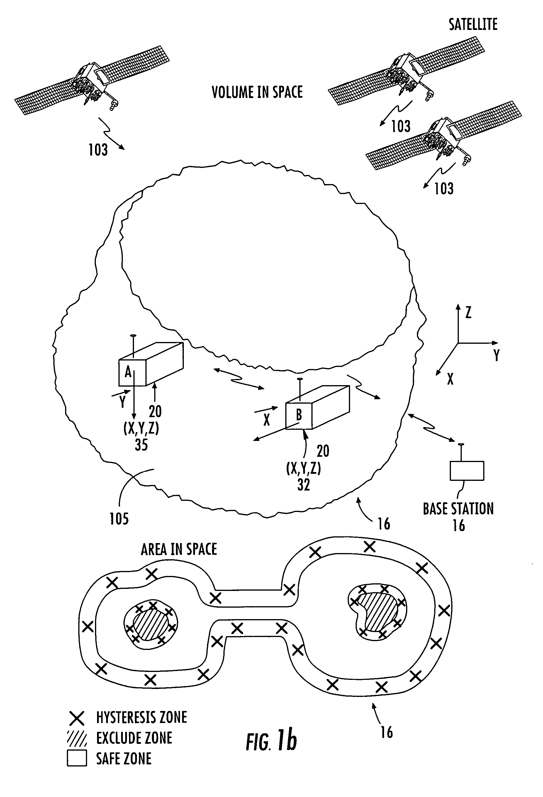
A collar to be worn on an object or a large or small animal has been designed incorporating (D)GPS technology. The operation of the device includes programming the three dimensional boundary into the memory of the device and simply installing the collar on the animal. As the animal approaches the preprogrammed boundary, a first alarm sounds when the subject is within an arbitrary user defined distance, and a second more drastic alarm such as a shock correction is applied when the subject approaches a second position closer to the boundary. Means to easily program the device are also included in the system. The device has the capability to call or transmit important information such as location, speed, identity, and medical parameters, etc. to a station automatically or when polled. All necessary analog and digital circuitry, microprocessor, programming, communications hardware are integrated into the collar. The device also has applications in land, air and sea navigation, farming, construction, tracking stolen vehicles, and keeping track of children. This device could also be embedded in a specialized lawnmower that would know where your yard ended and your neighbor's began, and traverse around all obstacles in the yard. Important Military applications would include warning and directing soldiers of front line boundaries, minefield mapping and 3-D direction around MOA's for aircraft.

Description

RELATED APPLICATION [0001] This application claims the benefit of U.S. Provisional Patent Application Ser. No. 60 / 258,246, filed Dec. 26, 2000; and is a continuing application of U.S. patent application Ser. No. 10 / 035,937, filed Dec. 26, 2001; the disclosure of which is incorporated herein by reference in its entirety.TECHNICAL FIELD [0002] This invention relates to defining and detection of a 3-D boundary or volume using (D)GPS (Global Positioning System) technology. In particular, it relates to an integrated instrument and method for inputting coordinates, processing these coordinates, and taking a corrective action with respect to the boundary. BACKGROUND ART [0003] The current practice and state of the art in the pet containment industry is to use radio waves to detect when a pet such as a dog has come too close to a boundary. In these systems, it is required that the pet owners bury a wire around the perimeter of the boundary and connect a modulated signal generator to the wir...

Claims


Application Information

Patent Timeline
IPC IPC(8): A01K15/04G01S19/17A01K15/02G01S19/34G08B21/02
CPCA01K15/023G01C21/005G08B21/18G08B21/023G08B21/0269G08B21/0211G08B21/0261G08B21/0277
Inventor TROXLER, ROBERT ERNEST
Owner INT RES INST
Learn More