Self-clinching cable tie mount

a self-clinching, cable tie technology, applied in the direction of pipe support, plastic deformation fastening, pipe/joint/fitting, etc., can solve the problems of the tendency to dislodge itself over time from the sheet panel, the final placement of the adhesive backed mount on the panel is quite often inconsistent, and the adhesive backing fails quite often. , to achieve the effect of improving the load bearing capability of the cable tie mount, reducing assembly time, and improving the positional accuracy

Inactive Publication Date: 2006-02-09
WINTON GEORGE R III
View PDF22 Cites 0 Cited by
  • Summary
  • Abstract
  • Description
  • Claims
  • Application Information

AI Technical Summary

Benefits of technology

[0011] (a) to improve the load bearing capability of a cable tie mount without the use of a screw;
[0012] (b) to reduce the assembly time for installing a cable tie mount for a high load application;
[0013] (c) to improve the positional accuracy of locating a cable tie mount; and

Problems solved by technology

The disadvantage of the Nicoli adhesive mount is its tendency to dislodge itself over time from the sheet panel.
The adhesive backing quite often fails when too much load is placed on the adhesive mount.
Also, the final placement of the adhesive backed mount on a panel is quite often inconsistent due to the installation process of simply laying the adhesive mount on a sheet panel.
The disadvantage of the Osada snap-action mount is it can only handle a limited amount of loading.
Also, the Osada mount does not display a flush surface on the far side of the sheet panel.

Method used


Image

  • Self-clinching cable tie mount
  • Self-clinching cable tie mount
  • Self-clinching cable tie mount

Examples


Embodiment Construction

[0027] Reference will now be made in detail to the present embodiments of the present invention, examples of which are illustrated in the accompanying drawings, wherein like reference numerals refer to the like elements throughout. The embodiments are described below in order to explain the present invention by referring to the figures.

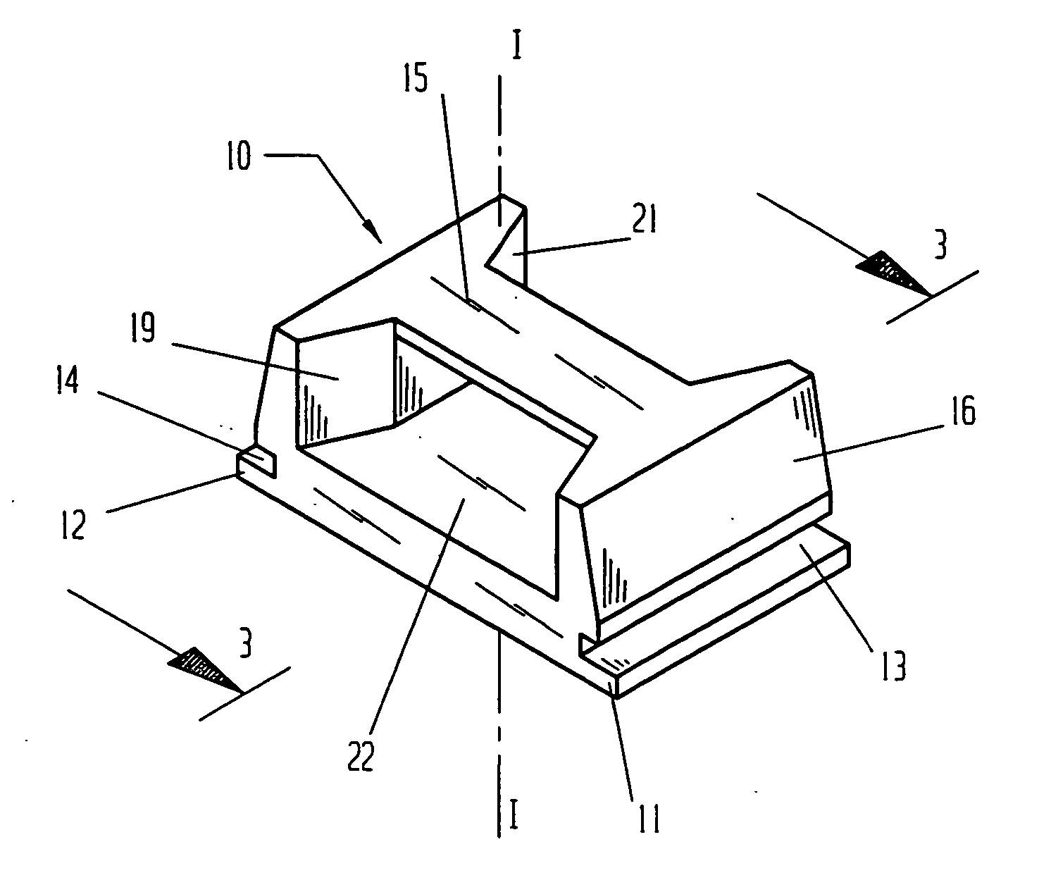
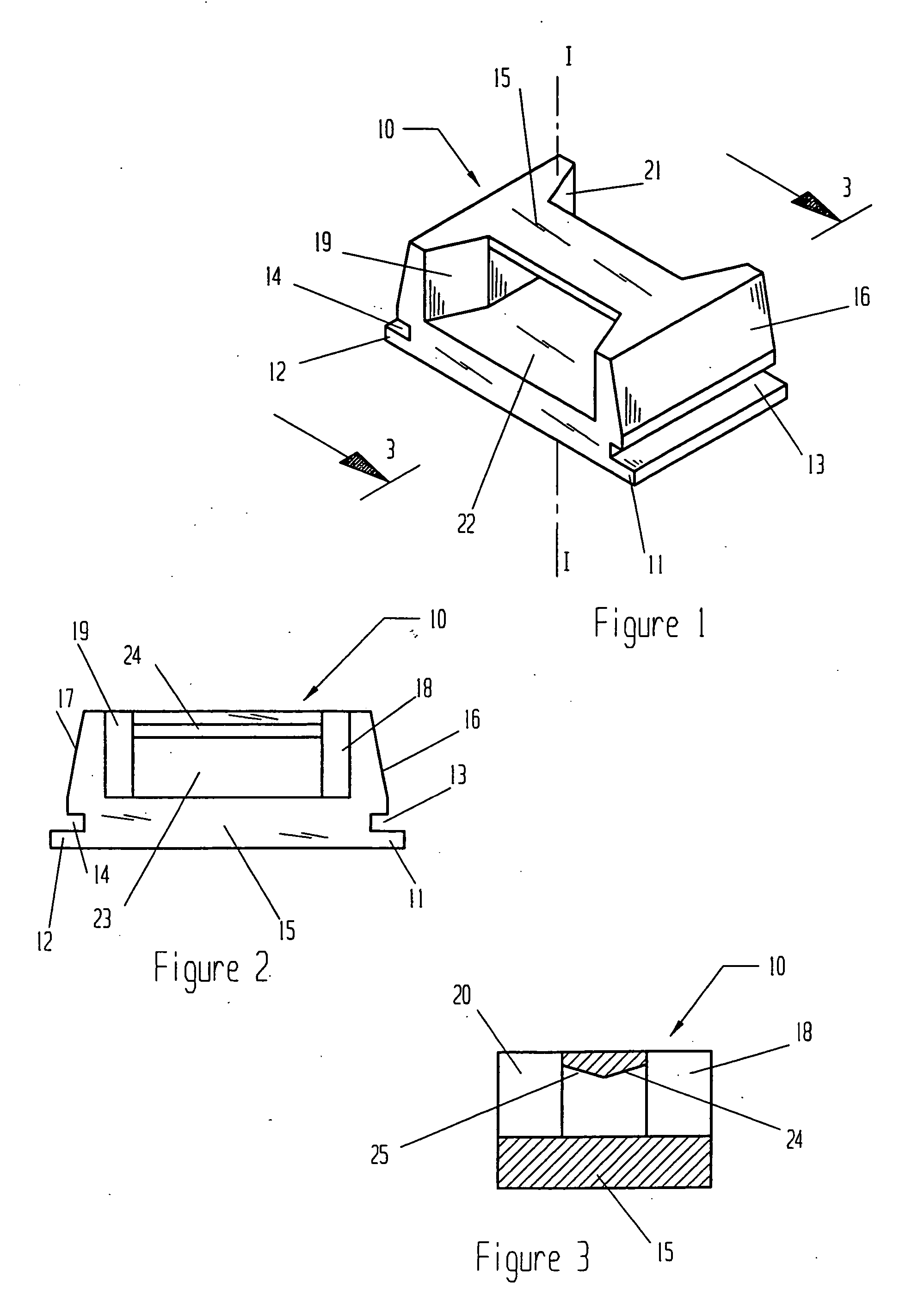
[0028] With initial reference to FIGS. 1 and 2, a self-clinching cable tie mount 10 is shown. Mount 10 has a body 15. Protruding outward and adjacent to body 15 are two extended lands 11 and 12. Extended land 11 and extended land 12 are set apart from one another. Both extended lands 11 and 12 are parallel to one another. Formed into body 15 are two undercut grooves 13 and 14. Undercut groove 13 and extended land 11 are adjacent and parallel to one another. Undercut groove 14 and extended land 12 are adjacent and parallel to one another. Body 15 joins extended lands 11 and 12 with undercut grooves 13 and 14.

[0029] From FIG. 2, body 15 has an externa...


PUM


Abstract

A self-clinching fastener that when pressed into a thin sheet panel provides for a strong attachment point for a cable tie. The inventive fastener relies on the self-clinching process to carry external loads and thus carries larger loads when compared to adhesive backed cable tie mounts. When installed, the self-clinching fastener becomes flush with the far side of the sheet panel.

Description

CROSS-REFERENCE TO RELATED APPLICATIONS [0001] This application is a continuation of application Ser. No. 10 / 309,124, filed Dec. 4, 2002 now pending, which is a continuation of application Ser. No. 10 / 028,218, filed Dec. 28, 2001, now abandoned, which is a continuation of application Ser. No. 09 / 618,609, filed Jul. 17, 2000, now U.S. Pat. No. 6,367,745.BACKGROUND OF THE INVENTION [0002] 1. Field of the Invention [0003] The present invention relates to self-clinching fasteners that provide for a secure mounting location for common cable ties. [0004] 2. Description of the Related Art [0005] Manufacturers of industrial machines quite often make use of wire harnesses to distribute electrical power to various locations within a machine. It is common to run bundles of wire along a sheet metal panel in order to distribute the bundles of wires. These bundles are often anchored to a sheet panel in discreet locations to prevent the wires from coming in contact with harmful elements. [0006] A ...

Claims


Application Information

Patent Timeline
Patent Type & Authority Applications(United States)
IPC IPC(8): F16L3/12F16L3/08F16L3/233
CPCF16B11/002F16L3/24F16L3/233F16L3/243
Inventor WINTON, GEORGE R. III
Owner WINTON GEORGE R III
Why Eureka
Try Eureka