Electromagnetic operation device

Inactive Publication Date: 2006-02-09
HITACHI LTD
View PDF0 Cites 13 Cited by
  • Summary
  • Abstract
  • Description
  • Claims
  • Application Information

AI Technical Summary

Benefits of technology

[0006] In addition, the size of the electromagnetic operator and its controller has become larger as electromagnet has become larger, which resultantly disables space saving.
[0007] In view of the above problems associated with the prior art,

Problems solved by technology

Consequently, there arises a problem that the shut-off timing of vacuum valve of each phase varies and so stable shut-off of the power system cannot be achieved.
In

Method used


Image

  • Electromagnetic operation device
  • Electromagnetic operation device
  • Electromagnetic operation device

Examples


first embodiment

[0019] (First Embodiment)

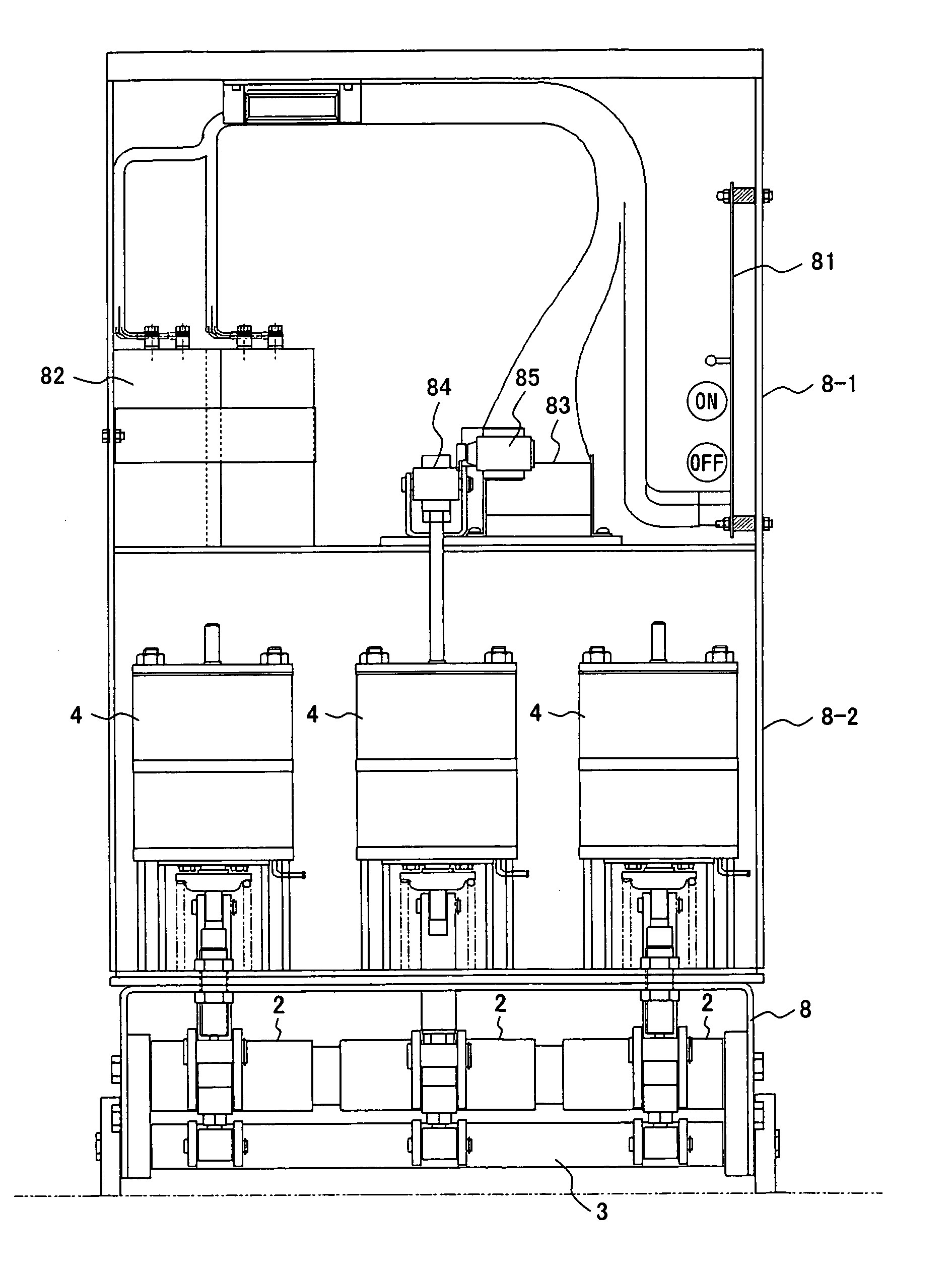
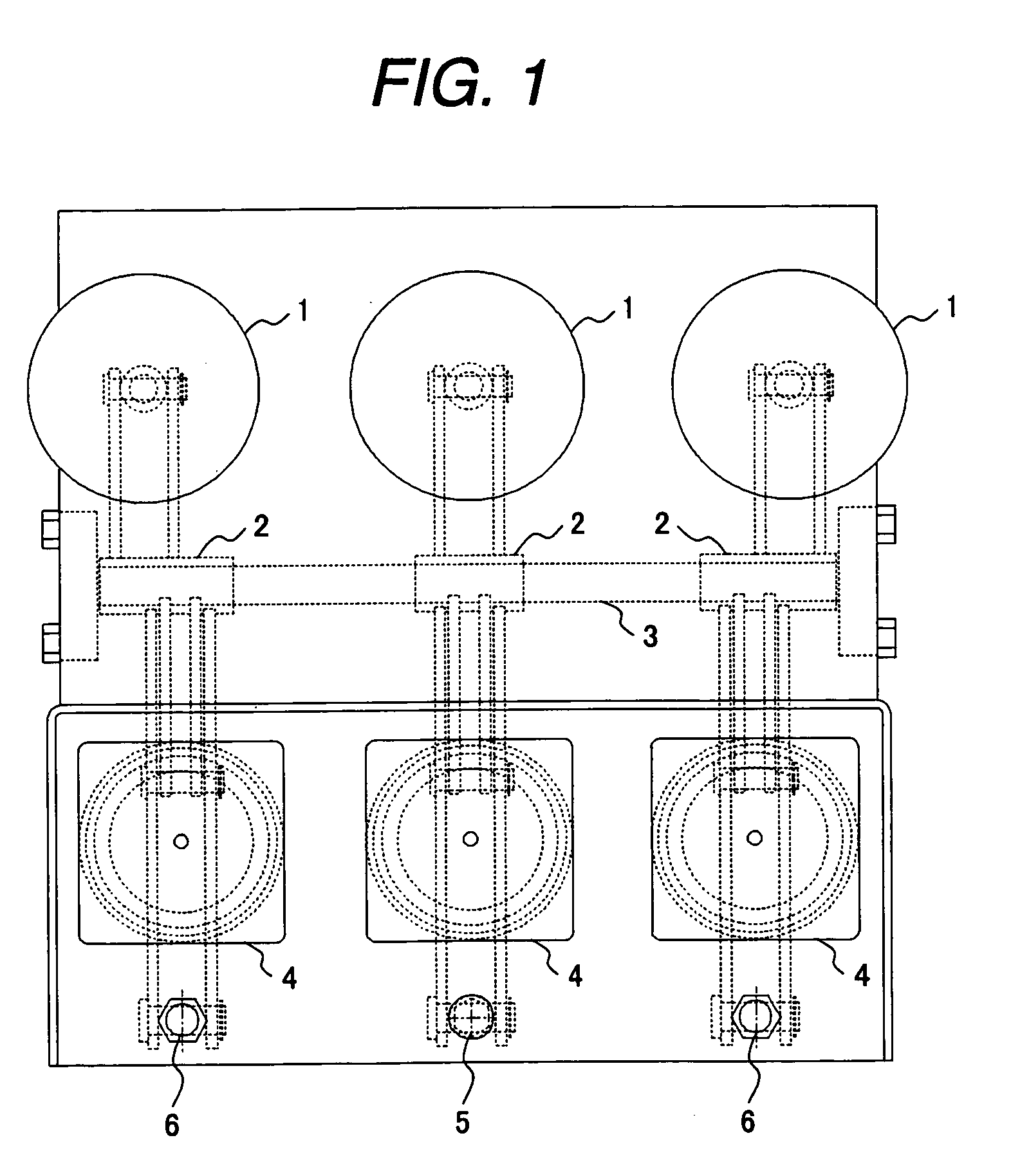
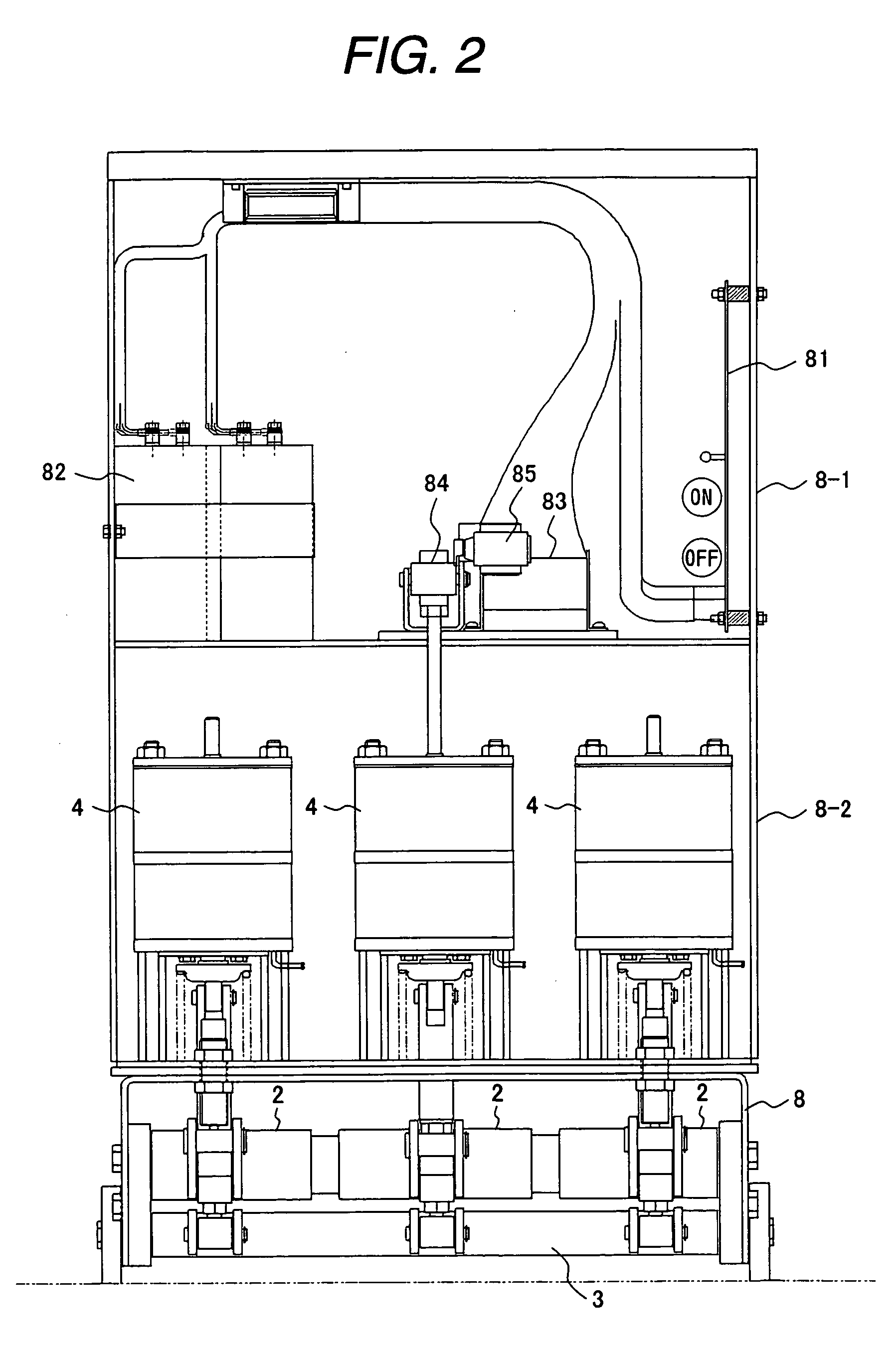
[0020]FIG. 1 is a plan view of the electromagnetic operation device of the present invention; FIG. 2 is a front view including electromagnetic operators and controller; FIGS. 3A and 3B are side view including the main shafts and three-phase connecting shaft.

[0021] As shown in FIG. 1, the vacuum valve 1 of each phase is connected with the electromagnetic operator 4 via the main shaft 2. Each main shaft 2 starts operation freely from other phases, but is connected with others by the three-phase connecting shaft 2 for synchronization.

[0022] As shown in FIG. 2, the electromagnetic operation device is enclosed in a multi-stage box case 8, where controller including a control board 81 and capacitor 82 are enclosed in the upper stage 8-1 and an electromagnetic operator 4 is enclosed in the middle stage 8-2. The upper stage 8-1 can not only be provided above the center electromagnetic operator 4 as shown in the figure but also be provided above other electromagnet...

second embodiment

[0035] (Second Embodiment)

[0036] Next, the second embodiment of the present invention is described hereunder. FIG. 5 and FIG. 6 show an embodiment where the three-phase connecting shaft 3 is provided above the electromagnetic operator 4.

[0037] The three-phase connecting shaft 3 is provided above the electromagnetic operator 4 and the main shaft 2 is provided below the electromagnetic operator 4. The two shafts are connected via the rod 44 of the electromagnetic operator 4. That is to say, because the rod 44 is connected with the blade 45 of the main shaft 2 at the fulcrum 46, the motion of the rod 44 is transmitted to the blade 47 of the three-phase connecting shaft 3. Accordingly, the three-phase connecting shaft 3 can synchronize the operation of the main shafts 3 of each phase.

third embodiment

[0038] (Third Embodiment)

[0039] Next, the third embodiment of the present invention is described hereunder. FIG. 7 shows an embodiment where the three-phase connecting shaft 3 is provided on the vacuum valve 1 side. This differs from the first embodiment in a point that the three-phase connecting shaft 3 is provided on the vacuum valve 1 side below the main shaft 2. The linkage 7 is provided between the blade 45′ on the vacuum valve 1 side of the main shaft and blade 47 of the three-phase connecting shaft. Linkage operation is the same as in the fist embodiment.

[0040] While any of the three embodiments described above shall be selected in accordance with the arrangement of the electromagnetic operation device, the first and third embodiments allow easier installation and adjustment because the main shafts and three-phase connecting shafts are provided in the same portion of the case. On the other hand, the second embodiment is advantageous in case space is available above the elect...


PUM


Abstract

An electromagnetic operation device, comprising electromagnetic operators each paired with a vacuum valve of each phase of three phases, is equipped with main shafts that can operate independently for each phase and a three-phase connecting shaft that synchronizes the operation of the three phases in accordance with the operation of each main shaft. The rod of the electromagnetic operator is connected with the blade of the main shaft at the fulcrum and the blade of the three-phase connecting shaft is connected with the blade of the main shaft by the linkage. The motion of a main shaft that has operated quicker than the others is transmitted to the other main shafts via the three-phase connecting shaft so as to synchronize the operation of the three phases.

Description

CLAIM OF PRIORITY [0001] The present application claims priority from Japanese application serial no. 2004-215789, filed on Jul. 23, 2004, the content of which is hereby incorporated by reference into this application. FIELD OF THE INVENTION [0002] The present invention relates to an electromagnetic operation device, particularly to the electromagnetic operation device that is suitable for switching a switch such as circuit breaker with the aid of electromagnetic force. BACKGROUND OF THE INVENTION [0003] To operate a switch such as circuit breaker, an electromagnetic operator that switches with the aid of electromagnetic force generated by electromagnet is utilized (see Japanese Patent Laid-open No. 2002-217026). [0004] There is also available a hybrid type operator on which electromagnetic suction force of electromagnet is used to turn on the switch and permanent magnet is employed to keep the switch on (see Japanese Patent Laid-open No. 2001-216875). SUMMARY OF THE INVENTION [0005...

Claims


Application Information

Patent Timeline
IPC IPC(8): H02K37/14
CPCH01H33/022H01H2033/6667H01H33/6662H01H33/38
Inventor SUGINO, TOMOHIROMORITA, AYUMUTSUCHIYA, KENJIKOBAYASHI, MASATO
Owner HITACHI LTD
Why Eureka
Try Eureka