Photoacoustic probe and photoacoustic imaging system

A technology of photoacoustic probe and ultrasonic probe, which is applied in ultrasonic/acoustic/infrasonic diagnosis, sonic diagnosis, infrasonic diagnosis, etc. It can solve problems such as unsatisfactory imaging effect, difficulty in exciting photoacoustic signal, incomplete light divergence, etc., to achieve simple Efficient delivery, increased size, ideal imaging effect

Active Publication Date: 2017-05-24
SHENZHEN INST OF ADVANCED TECH CHINESE ACAD OF SCI
View PDF8 Cites 6 Cited by
  • Summary
  • Abstract
  • Description
  • Claims
  • Application Information

AI Technical Summary

Problems solved by technology

Since the laser light coming out of the optical fiber 120 is only reflected by the aluminum foil 130 to the bottom of the ultrasonic probe, the light divergence of the laser light on the sample surface is not complete, and the ove

Method used


Image

  • Photoacoustic probe and photoacoustic imaging system
  • Photoacoustic probe and photoacoustic imaging system

Examples


Embodiment Construction

[0029] The following will clearly and completely describe the technical solutions in the embodiments of the present invention with reference to the accompanying drawings in the embodiments of the present invention. Obviously, the described embodiments are only some, not all, embodiments of the present invention. Based on the embodiments of the present invention, all other embodiments obtained by persons of ordinary skill in the art without creative efforts fall within the protection scope of the present invention.

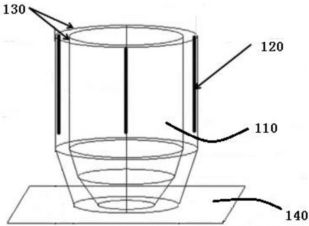
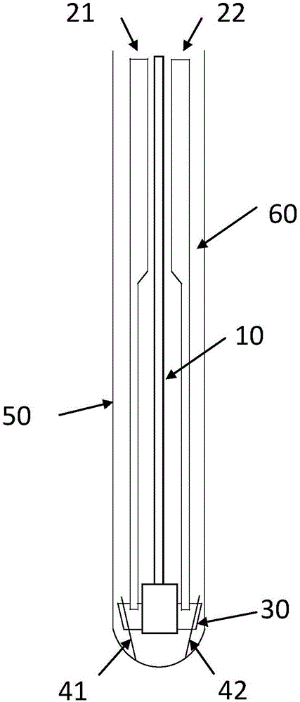
[0030] An embodiment of the present invention provides a photoacoustic probe, please refer to figure 2 , the photoacoustic probe includes an ultrasonic probe 10 , an optical fiber bundle, a reflection device and a cladding device 50 .

[0031] The ultrasonic probe 10 is used to detect the ultrasonic wave emitted by the sample, and convert the ultrasonic signal into an electrical signal for transmission. Specifically, when the laser irradiates the sample area, for ...


PUM


Abstract

The invention discloses a photoacoustic probe. The photoacoustic probe comprises an ultrasonic probe; an optical fiber bundle comprising a first optical fiber bundle and a second optical fiber bundle, wherein two optical fiber bundles are respectively positioned at two relative outer sides of the ultrasonic probe; a reflecting device positioned at the extension line of the tail end of the first optical fiber bundle and the tail end of the second optical fiber bundle, wherein the reflecting device is slantwise installed, and the distance from one end of the central shaft of the reflecting device adjacent to the optical fiber bundle to the central shaft of the ultrasonic probe is greater than the distance from one end of the central shaft of the reflecting device away from the optical fiber bundle to the central shaft of the ultrasonic probe, the reflecting device is used for reflecting the laser emitted by the first optical fiber bundle and the second optical fiber bundle to a sample, and the reflecting device is used for enabling the overlapping area of the illuminated area on the sample surface by the laser emitted by the first optical fiber bundle and the second optical fiber bundle and the detection area of the ultrasonic probe to be greater than 30% of the detection area. The invention further discloses a photoacoustic imaging system. The photoacoustic probe has the advantage of better imaging effect.

Description

technical field [0001] The invention relates to the field of imaging, in particular to a photoacoustic probe and a photoacoustic imaging system. Background technique [0002] Photoacoustic imaging is a new imaging method that combines the advantages of high sensitivity of optical imaging and depth of ultrasound imaging. Different from optical imaging, photoacoustic imaging detects ultrasonic waves generated by the photoacoustic effect, that is, pulsed laser beams irradiate the target area and are absorbed, which will cause an instantaneous temperature rise in the target area, and then generate ultrasonic waves that expand thermoelastically, and then collect ultrasonic waves The reconstructed image of the signal reflects the optical absorption properties of the substance. Optical technology imaging has great advantages in terms of resolution and so on. At the same time, the propagation attenuation of ultrasonic waves in biological tissues is much smaller than that of optica...

Claims


Application Information

Patent Timeline
IPC IPC(8): A61B5/00A61B8/00
CPCA61B5/0095A61B8/4444
Inventor 刘成波宋亮邢沐悦陈敬钦
Owner SHENZHEN INST OF ADVANCED TECH CHINESE ACAD OF SCI
Why Eureka
Try Eureka