Polarizer device for generating a defined spatial distribution of polarization states

a polarizer and spatial distribution technology, applied in the field of polarizer devices for generating a defined spatial distribution of polarization states, can solve the problem of relative cost of production, and achieve the effect of tolerable manufacturing outlay

Inactive Publication Date: 2006-02-09
CARL ZEISS SMT GMBH
View PDF14 Cites 44 Cited by
  • Summary
  • Abstract
  • Description
  • Claims
  • Application Information

AI Technical Summary

Benefits of technology

[0013] It is an object of the invention to provide a polarizer device for generating a light beam with a defined spatial polarization distribution, the production of which is relatively simple and cost-effective. It is another object to provide means to provide cylindrically symmetric distributions of locally differing privileged polarization directions, in particular radial polarization or tangential polarization, with a tolerable manufacturing outlay.

Problems solved by technology

The polarizer device designed as a space variant retarder, i.e. as a retardation device with a retardation effect varying over its cross section, operates in principle without losses but is relatively expensive to produce.

Method used


Image

  • Polarizer device for generating a defined spatial distribution of polarization states
  • Polarizer device for generating a defined spatial distribution of polarization states
  • Polarizer device for generating a defined spatial distribution of polarization states

Examples


Embodiment Construction

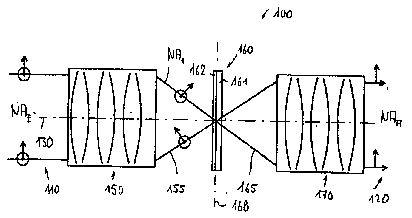
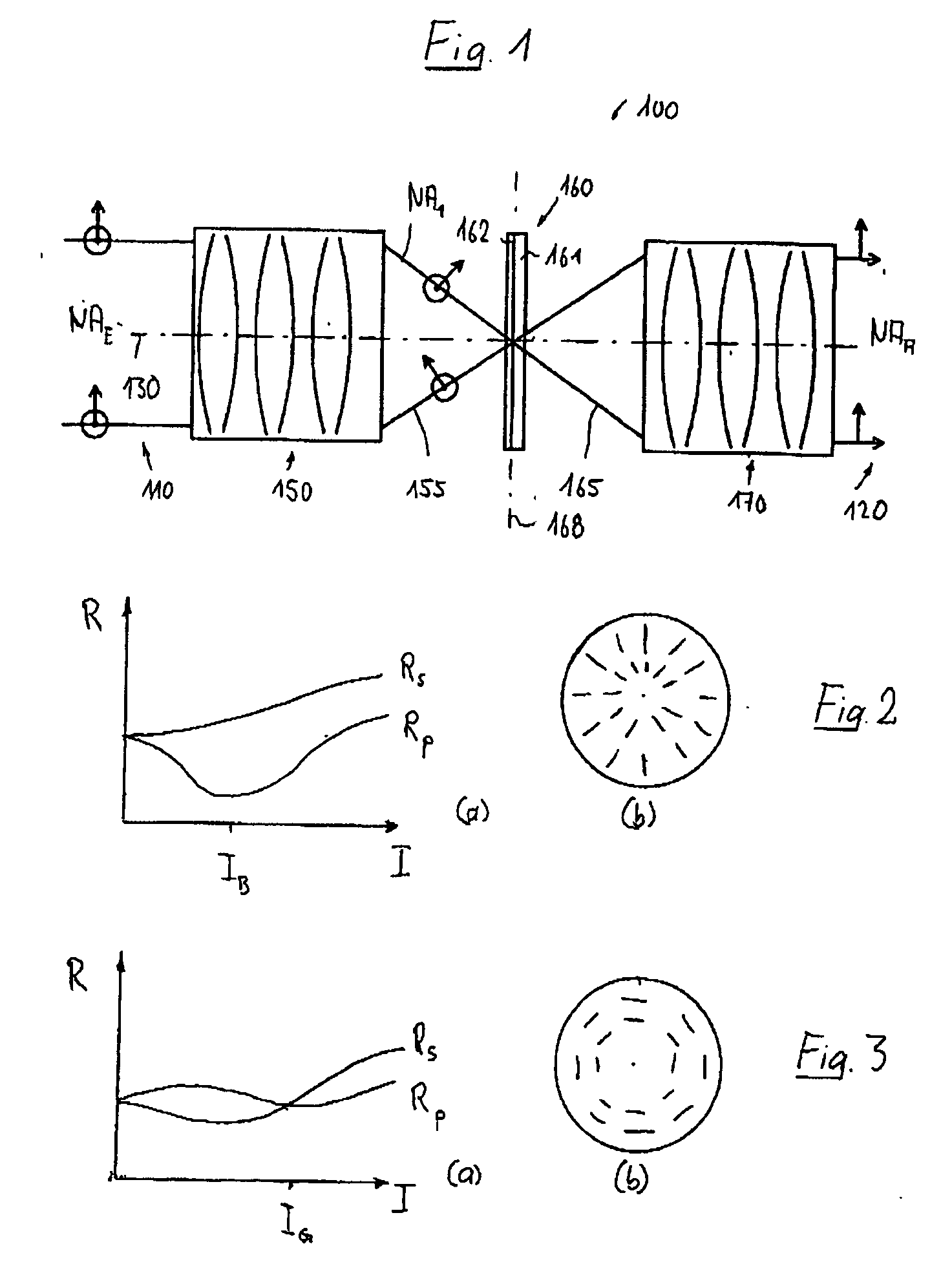
[0054]FIG. 1 schematically shows an embodiment of a polarizer device 100 which is designed to convert an entry light beam 110, which enters the polarizer device from the left in the representation, into an emerging (toward the right in the figure of the drawing) light beam 120 which has a defined position distribution of polarization states over the cross section of the exit light beam. The polarizer device, designed for the deep ultraviolet (DUV) range, is configured so that a substantially collimated entry light beam 110 with a numerical aperture NAEA130 of the system at any point of the cross section of the beam of rays (FIG. 2(b)).

[0055] The polarizer device comprises an angle varying input device 150, which may comprise one or more lenses with a positive refractive power and, with the aid of an overall positive refractive power, generates a convergent exit light beam 155 with a defined first angular distribution, which is characterized by a numerical aperture NA1>NAE, from the...


PUM


Abstract

A polarizer device, for converting an entry light beam into an exit light beam with a defined spatial distribution of polarization states, has an angle varying input device for receiving the entry light beam and for generating a first light beam with a predeterminable first angular distribution of light rays; an angle-selectively active polarization influencing device for receiving the first light beam and for converting the first light beam into a second light beam according to a defined angle function of the polarization state variation; and an angle varying output device for receiving the second light beam and for generating the exit light beam with a second angular distribution from the second light beam. In particular, polarization states with a radial or tangential polarization can be provided cost-effectively in this way.

Description

[0001] This application claims benefit from U.S. Provisional Application No. 60 / 585,842 filed on Jul. 8, 2004. The complete disclosure of that provisional application is incorporated into this application by reference.BACKGROUND OF THE INVENTION [0002] 1. Field of the Invention [0003] The invention relates to a polarizer device for converting an entry light beam into an exit light beam with a predeterminable spatial distribution of polarization states, and to an optical system which contains at least one such polarizer device. A preferred field of application is the microlithographic production of finely structured semiconductor components and other components with the aid of projection lithography. [0004] 2. Description of the related Prior Art [0005] Projection exposure apparatus for microlithography have been used for decades for the photolithographic production of semiconductor components and other finely structured components. They are used to project the pattern of a mask (ret...

Claims


Application Information

Patent Timeline
Patent Type & Authority Applications(United States)
IPC IPC(8): G02B26/00
CPCG02B5/3041G02B5/3091G03F7/70566G02B27/288G03F7/70108G02B27/286
Inventor TOTZECK, MICHAELFELDMAN, HEIKOGRUNER, TORALFSCHUSTER, KARL-HEINZGREIF-WUESTENBECKER, JOERN N.STROESSNER, ULRICHSCHERUEBL, THOMASHARNISCH, WOLFGANG
Owner CARL ZEISS SMT GMBH
Why Eureka
Try Eureka