Optical head device

Inactive Publication Date: 2006-02-09
NIDEC SANKYO CORP
View PDF1 Cites 2 Cited by
  • Summary
  • Abstract
  • Description
  • Claims
  • Application Information

AI Technical Summary

Benefits of technology

[0010] In view of the problems described above, the present invention may advantageously provide an optical head device which is capable of effectively radiating the heat generated in the laser beam emitting element while shock resistance is ensured.

Problems solved by technology

Especially, the heat radiation property of the resin body frame is inferior to that of a metal body frame.
Therefore, the above-mentioned prior arts have following problems.
Further, since the respective elements are adhesively fixed to the frame made of photosensitive glass or resin material, it is difficult to obtain a sufficient adhesive strength and the shock resistance of the optical head device decreases even at an ordinary temperature.
However, the heat radiation is not sufficient even in the structure of the optical head device which is disclosed in the latter prior art and thus a more effective measure for heat radiation is required.

Method used


Image

  • Optical head device
  • Optical head device
  • Optical head device

Examples


Embodiment Construction

[0027] Several embodiments of the present invention will be described in detail below with reference to the accompanying drawings.

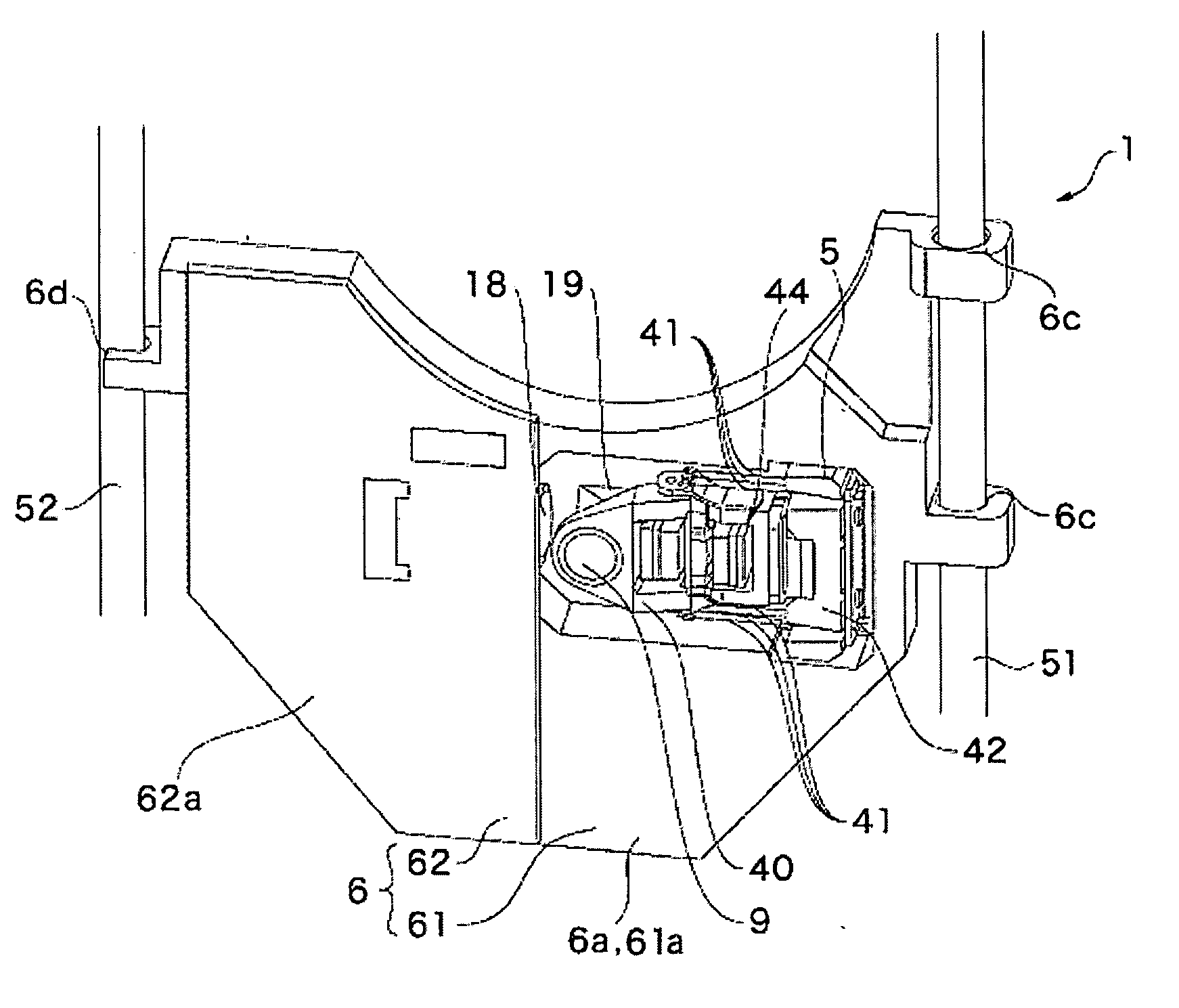
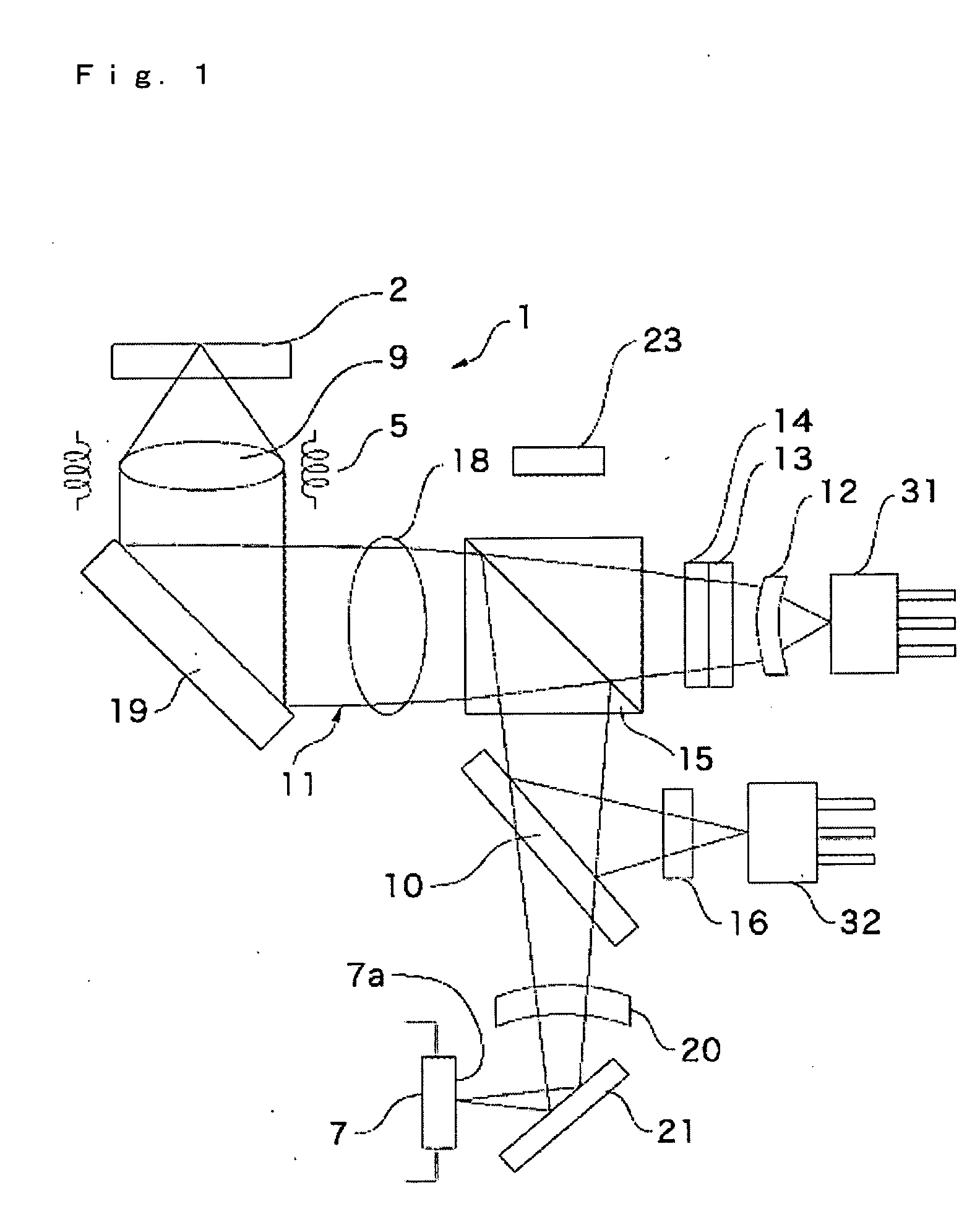
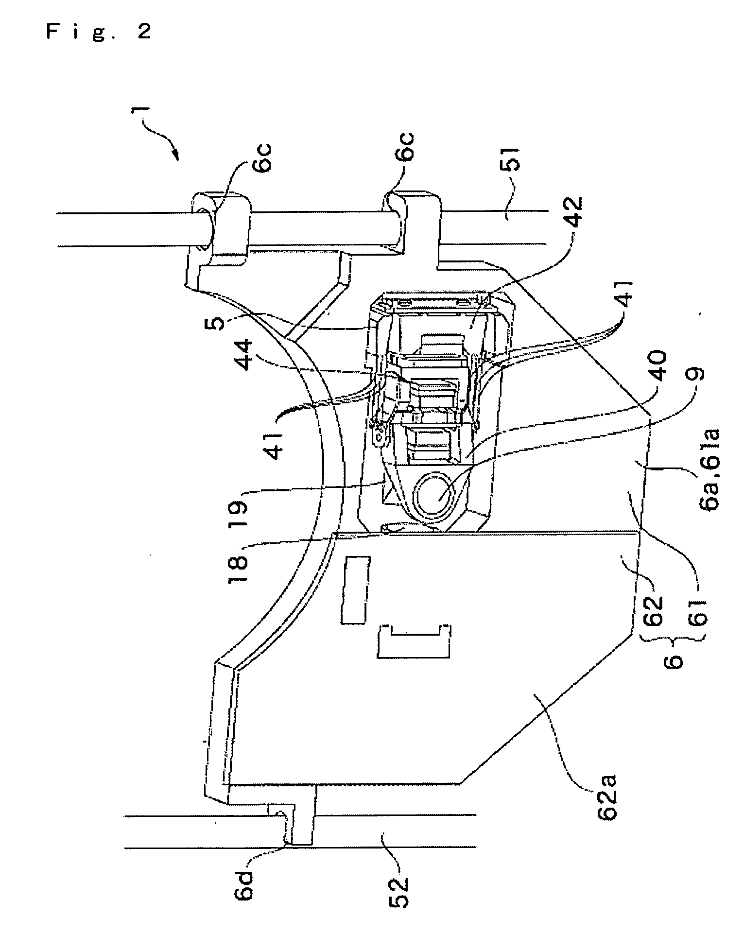
[0028]FIG. 1 is a schematic structural view showing an optical head device in accordance with an embodiment of the present invention. FIG. 2 is a perspective view showing the optical head device shown in FIG. 1 viewed from an upper face side. FIG. 3 is a perspective view showing the optical head device shown in FIG. 1 viewed from a bottom face side. FIG. 4 is a perspective view showing a state where optical elements are mounted on a metal frame of the optical head device shown in FIG. 1 viewed from the bottom face side.

[0029] An optical head device 1 in accordance with an embodiment of the present invention is used for recording and reproducing information in and from an optical disk 2 such as a CD or a DVD. The optical head device 1 includes a first and a second laser beam emitting elements 31, 32 as light sources for emitting laser beams to the optica...


PUM


Abstract

An optical head device includes a laser beam emitting element, a light receiving element, an optical system which guides an emitted light beam from the laser beam emitting element to the optical disk and guides the reflected light beam from the optical disk to the light receiving element, and a main body frame on which the laser beam emitting element, the light receiving element and the optical system are mounted. The main body frame is constructed of a metal frame and a resin frame. The optical system, the laser beam emitting element and the light receiving element are attached to the metal frame and the metal frame is attached to the resin frame.

Description

CROSS REFERENCE TO RELATED APPLICATION [0001] The present invention claims priority under 35 U.S.C. §119 to Japanese Application No. 2004-232721 filed Aug. 9, 2004, which is incorporated herein by reference. FIELD OF THE INVENTION [0002] An embodiment of the present invention may relate to an optical head device for performing recording and reproduction in and from an optical disk such as a CD or a DVD. More specifically, an embodiment of the present invention may relate to the structure of a main body frame of the optical head device. BACKGROUND OF THE INVENTION [0003] An optical head device which performs recording and reproduction in and from an optical disk such as a CD or a DVD includes a laser beam emitting element which emits a laser beam to the optical disk, a light receiving element which receives a reflected light from the optical disk, an optical system which guides the emitted light beam from the laser beam emitting element to the optical disk and guides the reflected li...

Claims


Application Information

Patent Timeline
IPC IPC(8): G11B7/00G02B7/00
CPCG11B7/1376G11B7/08
Inventor WADE, TATSUKI
Owner NIDEC SANKYO CORP
Why Eureka
Try Eureka