
Heat radiating quartz plate, polarizing plate, and optical apparatus

Inactive Publication Date: 2006-10-12
TOYO TSUSHINKI
View PDF4 Cites 0 Cited by
  • Summary
  • Abstract
  • Description
  • Claims
  • Application Information

AI Technical Summary

Benefits of technology

[0009] An advantage of some aspects of the invention is that it provides a heat radiating quartz plate, a polarizing plate, and an optical mechanism, which can significantly improve heat radiating efficiency without increasing the area of the quartz plate, to radiate heat generated from the polarizing plate that is disposed and used in a liquid crystal panel of an optical system of a liquid crystal projector or the like.
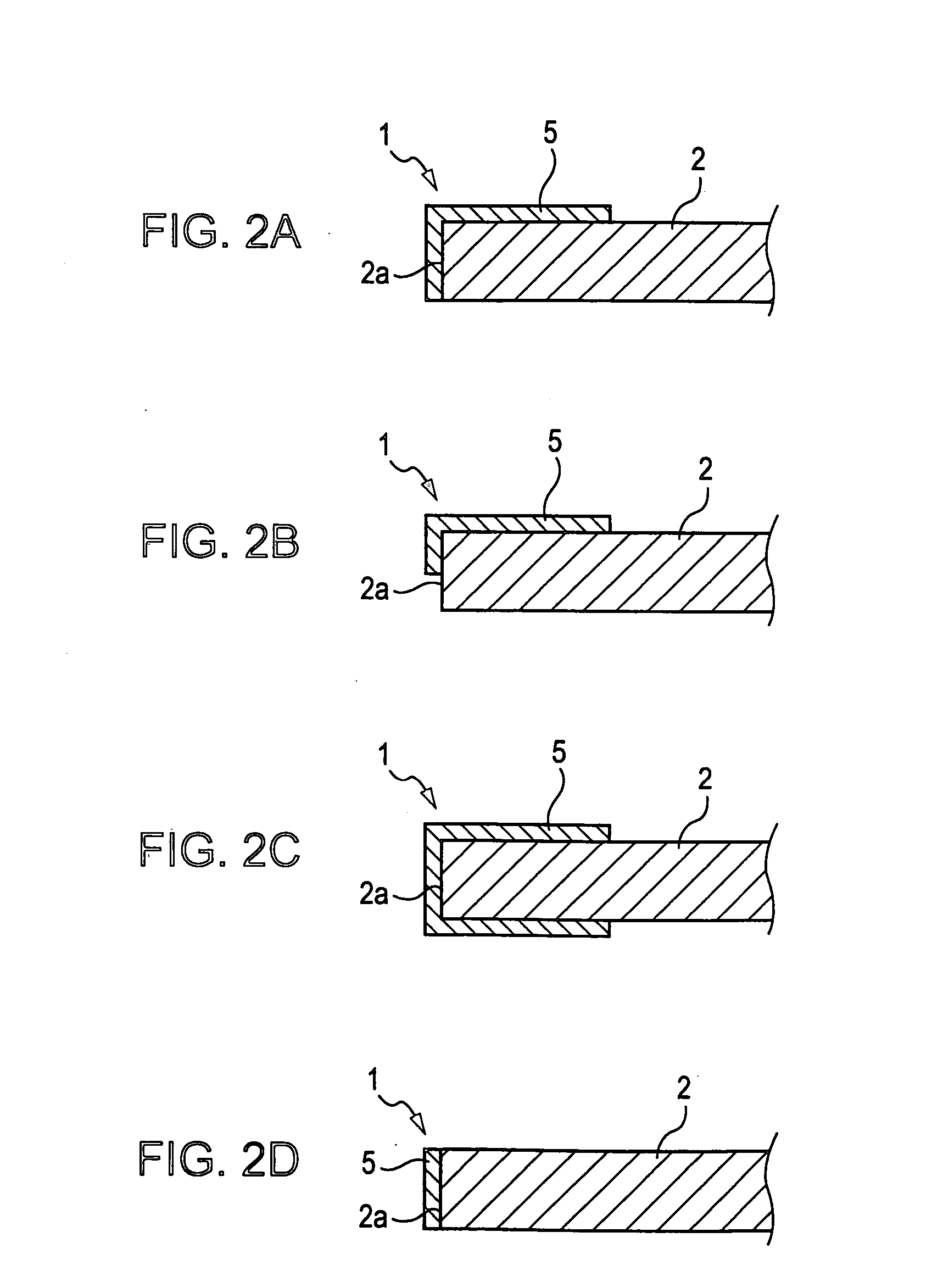
[0015] According to the aspects of the invention, in a quartz plate which is disposed on a polarizing plate, for effectively radiating heat of the polarizing plate disposed and used in a liquid crystal projector, a metal film is disposed along an outer periphery of a quartz plate which corresponds to the outside of an effective optical range of the quartz plate. Therefore, it is possible to improve the heat radiating efficiency without increasing the area of the heat radiating quartz plate.

Problems solved by technology

The polarizing plate generates heat when light components other than a light component in a direction of the polarizing axis are blocked off, but the polarizing plate is prone to be distorted or deteriorated by the generated heat, which may degrade optical characteristics of the polarizing plate.
In order to solve the problems, according to the related art, a transparent glass plate is bonded to the polarizing plate, but heat radiating efficiency is not sufficient for the glass plate.
However, it is difficult to manufacture the sapphire substrate and it is expensive to manufacture the sapphire substrate.
As a result, there is limitation in improving heat radiating efficiency while satisfying the demands of miniaturization, high integration, and high output of various optical components of a liquid crystal projector.

Method used


Image

  • Heat radiating quartz plate, polarizing plate, and optical apparatus
  • Heat radiating quartz plate, polarizing plate, and optical apparatus
  • Heat radiating quartz plate, polarizing plate, and optical apparatus

Examples


Embodiment Construction

[0031] Hereinafter, a preferred embodiment of the invention will be described with reference to the accompanying drawings.

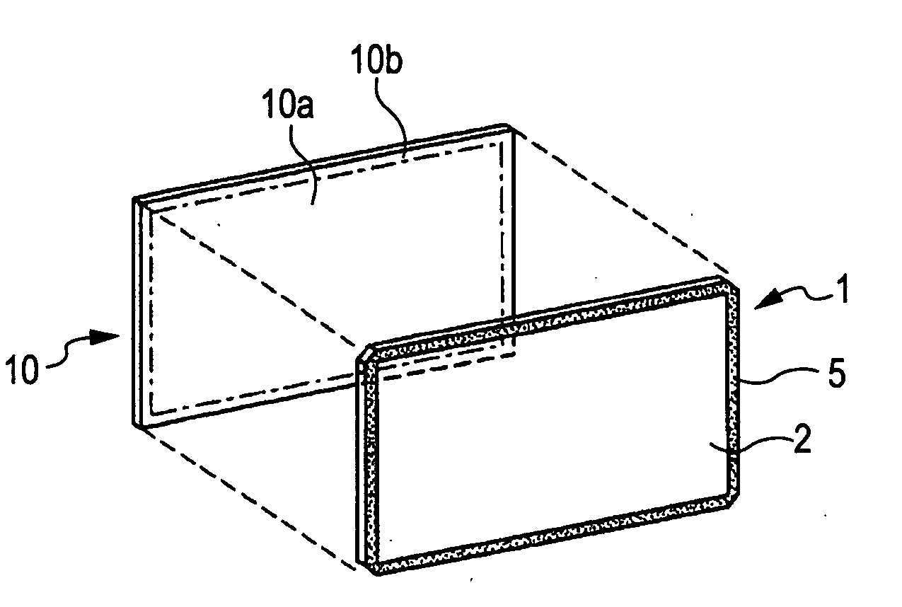
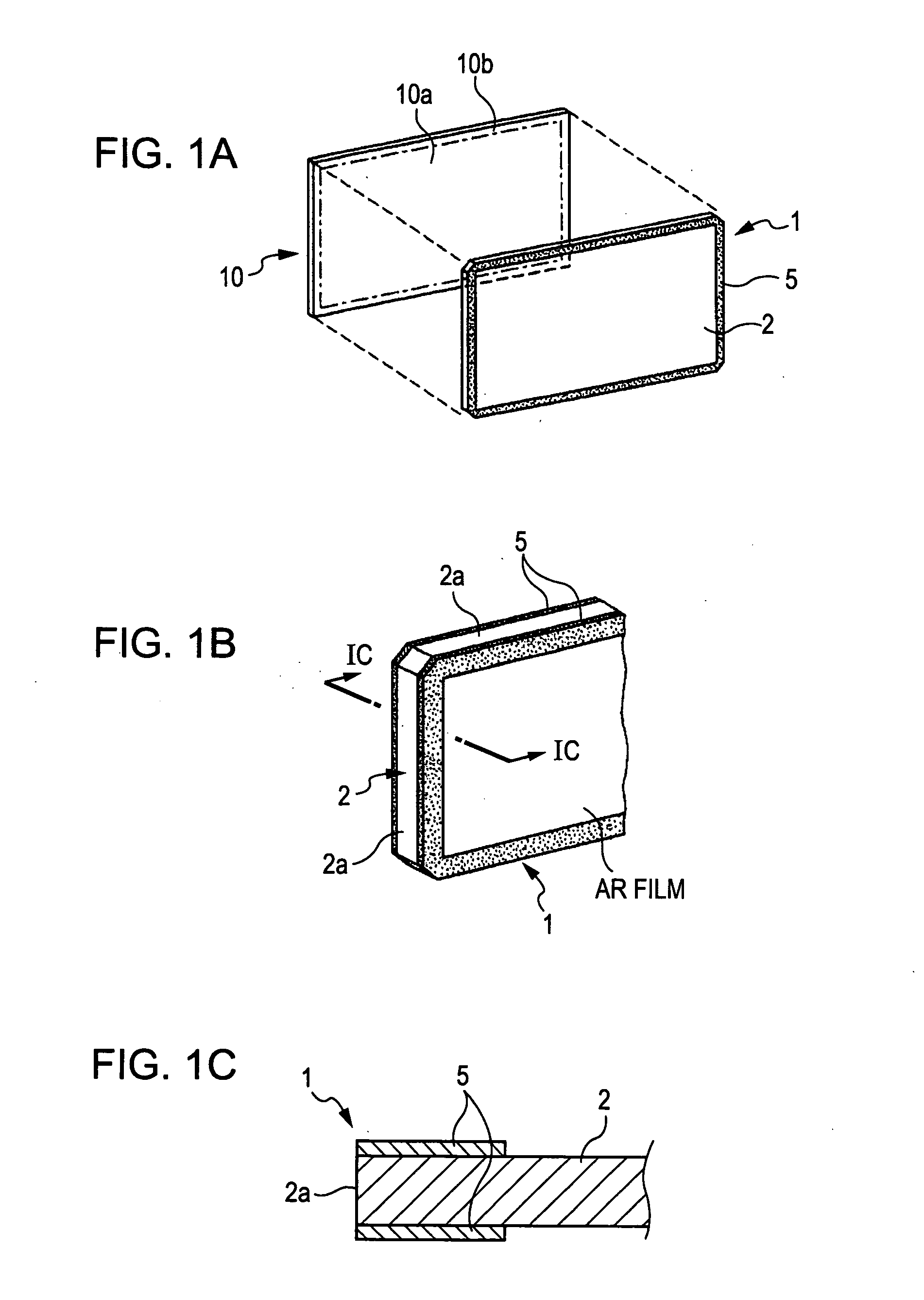
[0032]FIG. 1A is an exploded perspective view showing the relationship between a heat radiating quartz plate and a polarizing plate according to a first embodiment of the invention, FIG. 1B is a main perspective view showing the configuration of the heat radiating quartz plate, and FIG. 1C is a cross-sectional view showing the heat radiating quartz plate taken along the line IC-IC of FIG. 1B. A heat radiating quartz plate 1 is, for example, heat radiating means to be disposed on one side or both sides of a polarizing plate 10 in order to improve heat radiating efficiency of the polarizing plate 10 which is disposed on either side of an incident surface or a light-emitting surface of a liquid crystal panel in a liquid crystal projector, and a metal film 5 is disposed along an outer periphery of a quartz plate 2 which corresponds to the outside 10b of an effective...


PUM


Abstract

A heat radiating quartz plate is disposed on the surface of a polarizing plate. In the heat radiating quartz plate, a metal film is disposed along an outer periphery of a quartz plate which corresponds to the outside of an effective optical range of the polarizing plate.

Description

BACKGROUND [0001] 1. Technical Field [0002] The present invention relates to a heat radiating quartz plate which is disposed on a polarizing plate, for efficiently radiating heat generated from the polarizing plate used in a liquid crystal projector, and the polarizing plate having the heat radiating quartz plate. Further, the invention relates to an improvement of an optical apparatus having the polarizing plate. [0003] 2. Related Art [0004] A liquid crystal projector has a structure, in which light emitted from a light source is modulated according to image information by using a liquid crystal light valve and the modulated light is projected onto a screen. The liquid crystal light valve is formed such that a polarizing plate is bonded to an incident surface of the liquid crystal panel or a light-emitting surface of the liquid crystal panel and light from the light source is converted into a polarized light by the polarizing plate so as to use the light efficiently. The polarizing...

Claims


Application Information

Patent Timeline
IPC IPC(8): G02B6/00
CPCG02B7/008G02B5/3025
Inventor ISOMURA, TOMOKIMATSUMOTO, HIROSHI
Owner TOYO TSUSHINKI
Learn More