
Abrasive grindstone

Inactive Publication Date: 2016-08-18
DISCO CORP
View PDF2 Cites 2 Cited by
  • Summary
  • Abstract
  • Description
  • Claims
  • Application Information

AI Technical Summary

Benefits of technology

The present invention aims to provide an abrasive grindstone that can reduce grinding load, improve heat radiation, and have a longer life. This would result in improved productivity.

Problems solved by technology

Further, heat generated by grinding is not radiated from the abrasive grindstone, but accumulated therein, so that a grinding speed cannot be increased.

Method used


Image

  • Abrasive grindstone
  • Abrasive grindstone
  • Abrasive grindstone

Examples


Embodiment Construction

[0017]A preferred embodiment of the present invention will now be described in detail with reference to the drawings. The present invention is not limited to the preferred embodiment. Further, the components used in the preferred embodiment may include those that can be easily assumed by persons skilled in the art or substantially the same elements as those known in the art. Further, the configurations described below may be suitably combined. Further, the configurations may be variously omitted, replaced, or changed without departing from the scope of the present invention.

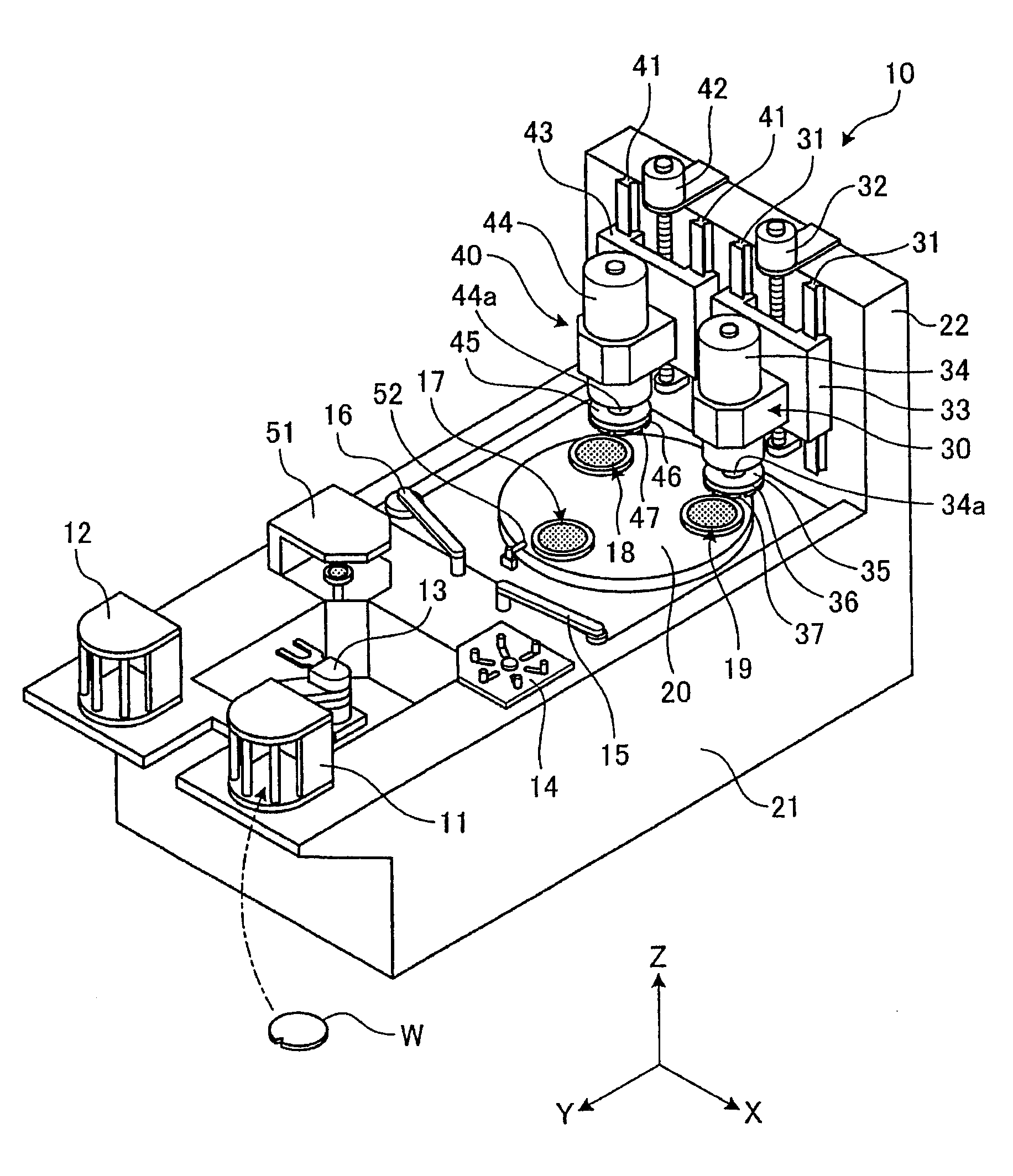
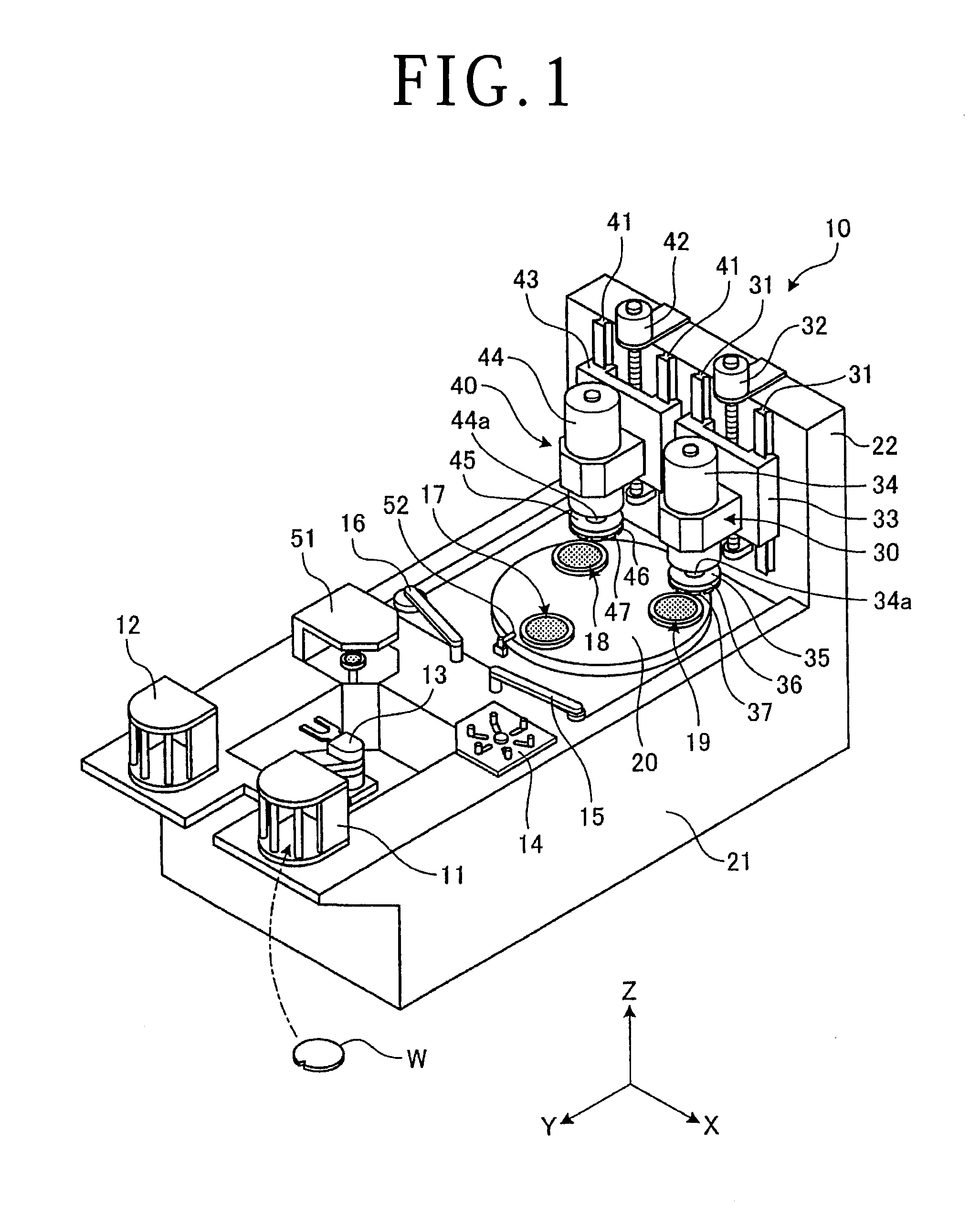
[0018]FIG. 1 is a perspective view showing the configuration of a grinding apparatus including an abrasive grindstone according to a preferred embodiment of the present invention. In FIG. 1, the X direction shown by an arrow X is the same as the lateral direction of a grinding apparatus 10, the Y direction shown by an arrow Y is the same as the longitudinal direction of the grinding apparatus 10, and the Z direct...


PUM


Abstract

An abrasive grindstone for grinding a workpiece is disclosed. The abrasive grindstone includes diamond abrasive grains and a boron compound. The diamond abrasive grains and the boron compound are compounded at a predetermined volume ratio. The average grain size Y of the diamond abrasive grains is set to 0 μm<Y≦50 μm. The average grain size ratio Z of the boron compound to the diamond abrasive grains is set to 0.8≦Z≦3.0. Preferably, the workpiece is a silicon wafer, and the average grain size ratio Z is set to 0.8≦Z≦2.0.

Description

BACKGROUND OF THE INVENTION[0001]1. Field of the Invention[0002]The present invention relates to an abrasive grindstone for grinding a workpiece.[0003]2. Description of the Related Art[0004]An abrasive grindstone containing a boron compound is used to grind a workpiece formed of a hard brittle material (see Japanese Patent Laid-Open No. 2012-56013, for example). The boron compound has a solid lubricating property and it is therefore considered that the boron compound functions to suppress the consumption of the abrasive grindstone due to grinding of the workpiece.SUMMARY OF THE INVENTION[0005]When a grinding load on the abrasive grindstone is high in grinding a workpiece formed of any material inclusive of a hard brittle material, the consumption of the abrasive grindstone is also high in general, so that the frequency of replacement of the abrasive grindstone is increased. Further, heat generated by grinding is not radiated from the abrasive grindstone, but accumulated therein, so ...

Claims


Application Information

Patent Timeline
IPC IPC(8): B24D3/34
CPCB24D3/34B24D3/00B24D3/10B24D3/14B24D3/28B24D7/06B24D3/06
Inventor OSHIMA, RYUJIMAJI, RYOGO
Owner DISCO CORP
Learn More