Evaporation source and method of depositing thin film using the same

Inactive Publication Date: 2007-06-28
SAMSUNG DISPLAY CO LTD
View PDF14 Cites 39 Cited by
  • Summary
  • Abstract
  • Description
  • Claims
  • Application Information

AI Technical Summary

Benefits of technology

[0012]It is therefore a feature of an embodiment of the present invention to provide an evaporation source and a method employing the same having the capability of minimizing the coalescence of the evaporated deposition material, thereby improving uniformity of thin deposition layers.
[0013]It is another feature of an embodiment of the present invention to provide an evaporati

Problems solved by technology

However, the particles of the evaporated deposition material may have a tendency to coalesce and form clusters of particles having various sizes, thereby providing an evaporated deposition material having non-uniform texture and density consistency.
Further, such non-uniform evaporated deposition material may cause application of non-uniform layers of deposition material onto substrates, thereby producing films lacking uniform thickness.
Additionally, application of the evapo

Method used


Image

  • Evaporation source and method of depositing thin film using the same
  • Evaporation source and method of depositing thin film using the same
  • Evaporation source and method of depositing thin film using the same

Examples


Example

[0027]Korean Patent Application No. 2005-0131489, filed on Dec. 28, 2005, in the Korean Intellectual Property Office, and entitled: “Evaporation Source and Method of Depositing Thin Film Using the Same,” is incorporated by reference herein in its entirety.

[0028]The present invention will now be described more fully hereinafter with reference to the accompanying drawings, in which exemplary embodiments of the invention are illustrated. The invention may, however, be embodied in different forms and should not be construed as limited to the embodiments set forth herein. Rather, these embodiments are provided so that this disclosure will be thorough and complete, and will fully convey the scope of the invention to those skilled in the art.

[0029]In the figures, the dimensions of layers and elements may be exaggerated for clarity of illustration. It will also be understood that when a layer or element is referred to as being “on” another layer, element, or substrate, it can be directly on...


PUM

PropertyMeasurementUnit
Deposition rateaaaaaaaaaa
Environmental propertiesaaaaaaaaaa
Evaporation enthalpyaaaaaaaaaa

Abstract

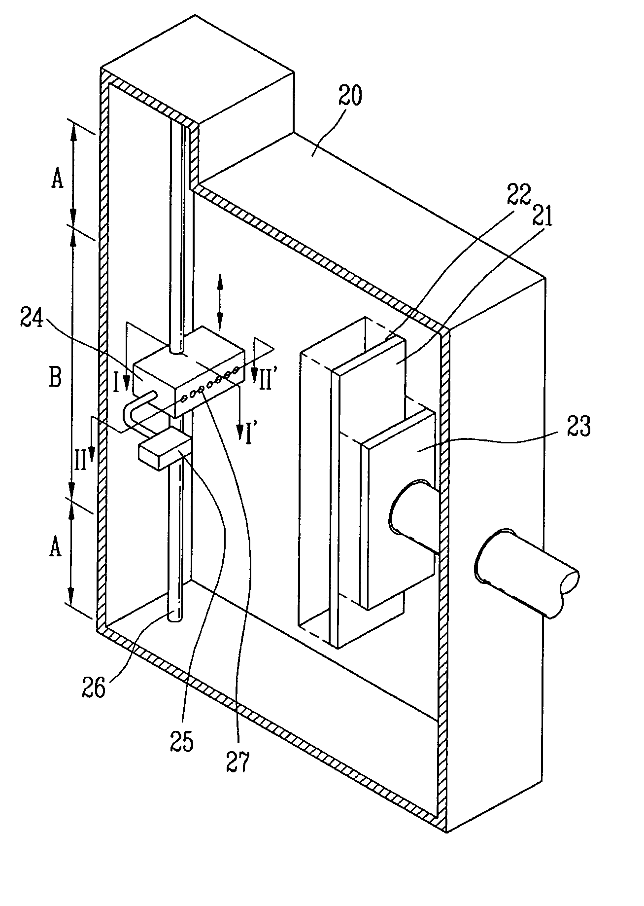
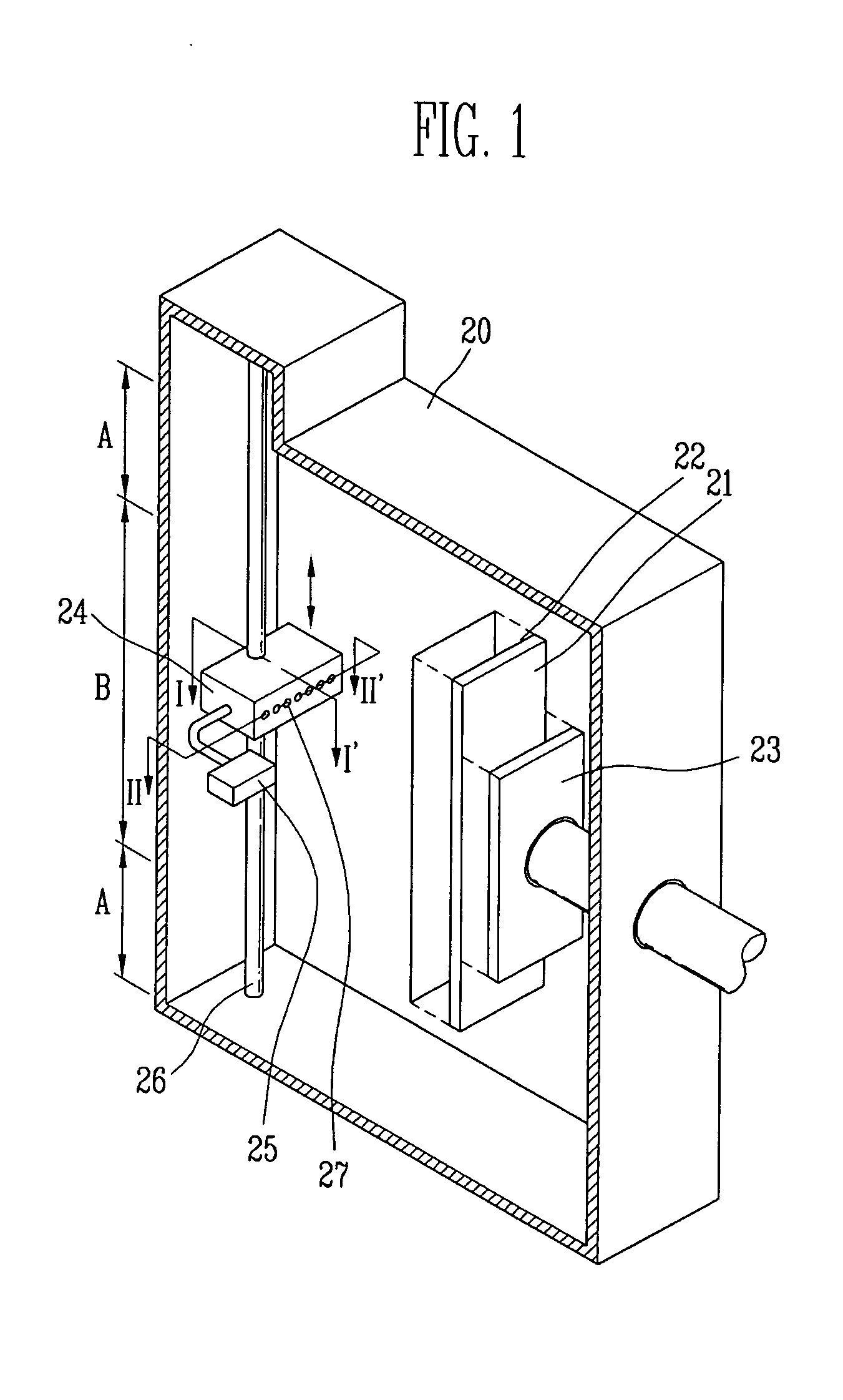
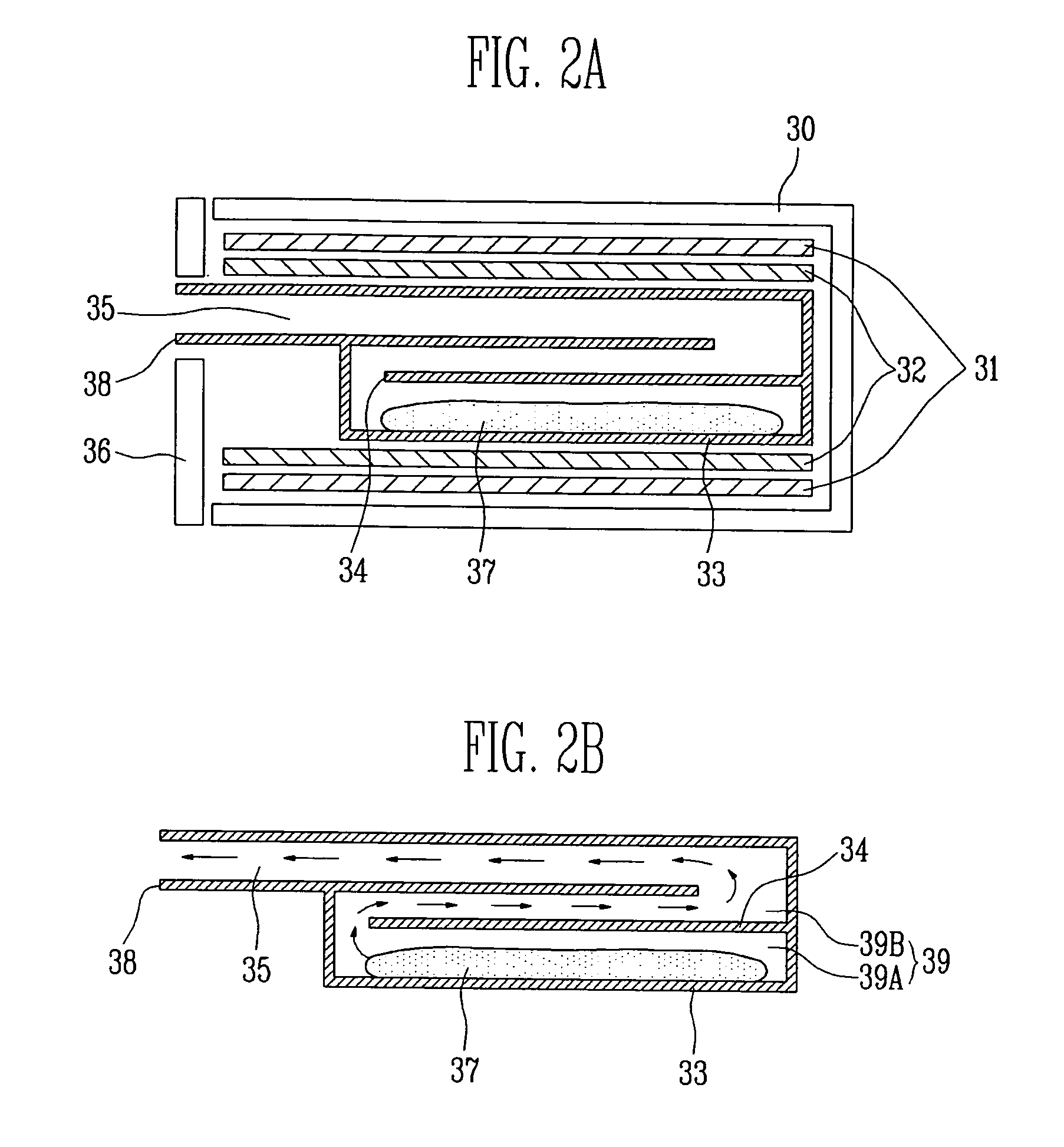
An evaporation source and method for depositing a thin film, including a crucible having a predetermined space for placing a deposition material and at least one baffle, the baffle positioned inside the crucible and parallel to the predetermined space to divide the crucible into a plurality of channels, a heating unit, and at least one spray nozzle in fluid communication with the crucible, the spray nozzle having a plurality of spray orifices.

Description

BACKGROUND OF THE INVENTION[0001]1. Field of the Invention[0002]The present invention relates to an evaporation source and a method for depositing thin films using the same. In particular, the present invention relates to an evaporation source and method for depositing thin films capable of providing uniform film thickness and minimized heat radiation.[0003]2. Discussion of the Related Art[0004]Deposition of thin films has numerous manufacturing applications. In semiconductor manufacturing, for example, thin films may be deposited in display devices, such as electroluminescent (EL) display devices, to provide photon-emitting mediums to form images.[0005]Such thin films may be applied to a substrate, e.g., an electrode, by methods such as physical vapor deposition (PVD), e.g., vacuum deposition, chemical vapor deposition (CVD), ion plating, sputtering, and so forth. In the vacuum deposition method, for example, a vacuum environment, e.g., vacuum chamber, may be provided with a substr...

Claims


Application Information

Patent Timeline
IPC IPC(8): C23C16/00
CPCC23C14/12C23C14/243C23C14/34C23C16/00C23C14/246C23C14/26H01L21/203
Inventor HUH, MYUNG SOOFURUNO, KAZUOHAN, SANG JINAHN, JAE HONGJEONG, SEOK HEON
Owner SAMSUNG DISPLAY CO LTD
Why Eureka
Try Eureka