Disk brake device for vehicle
- Summary
- Abstract
- Description
- Claims
- Application Information
AI Technical Summary
Benefits of technology
Problems solved by technology
Method used
Image
Examples
first embodiment
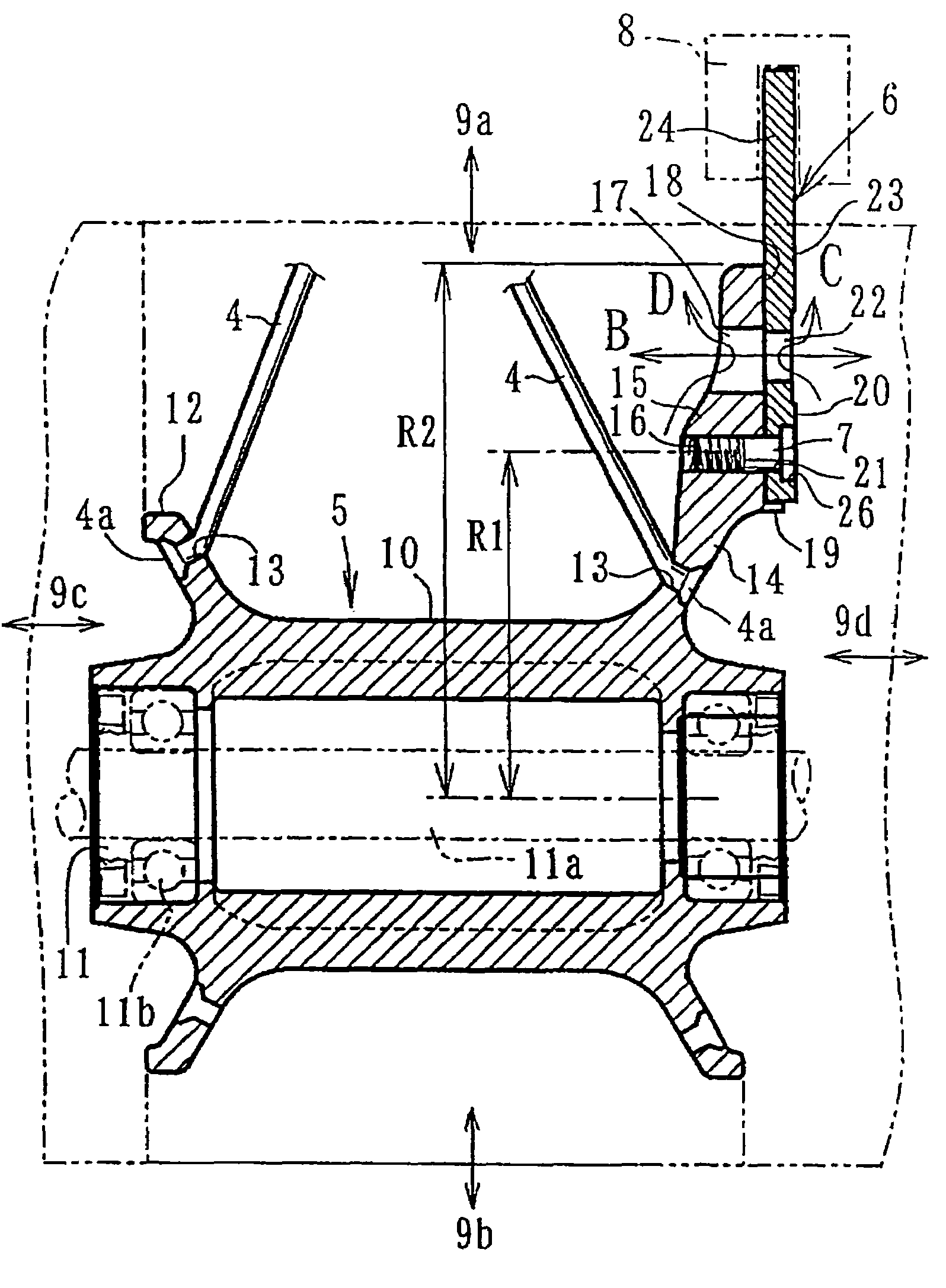
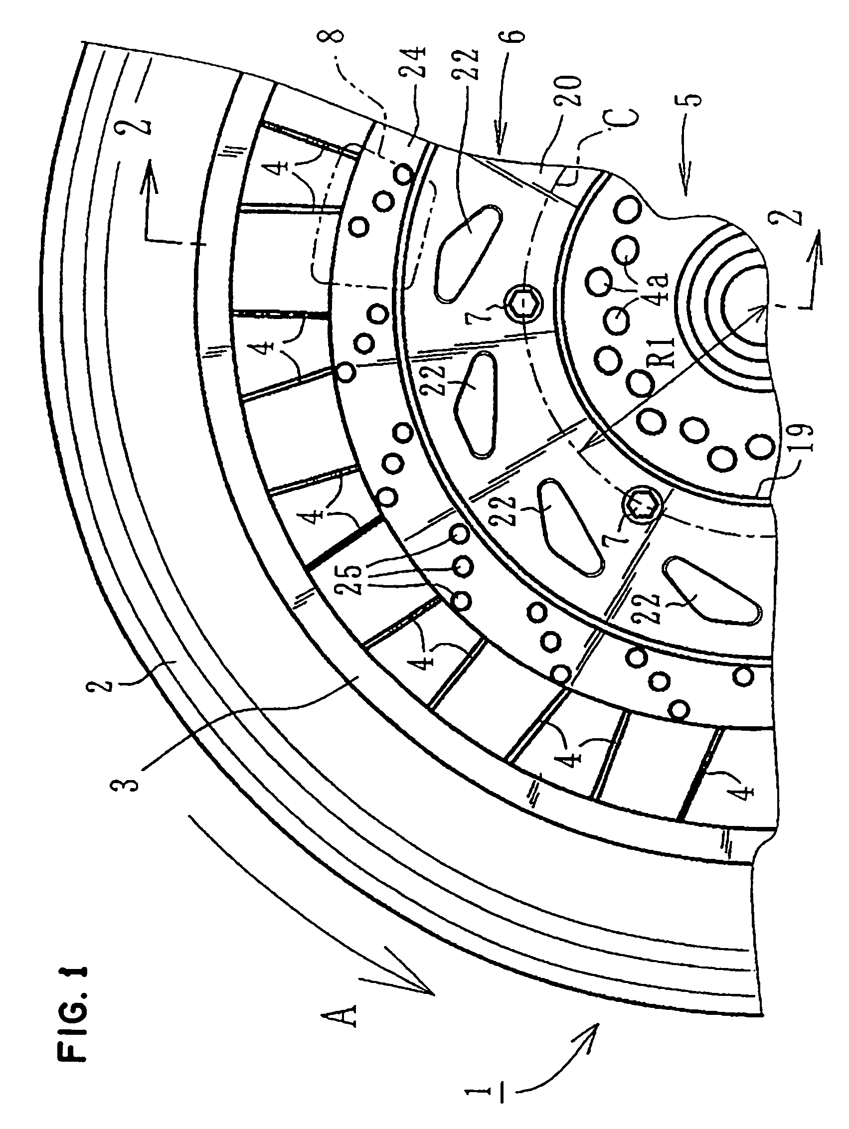
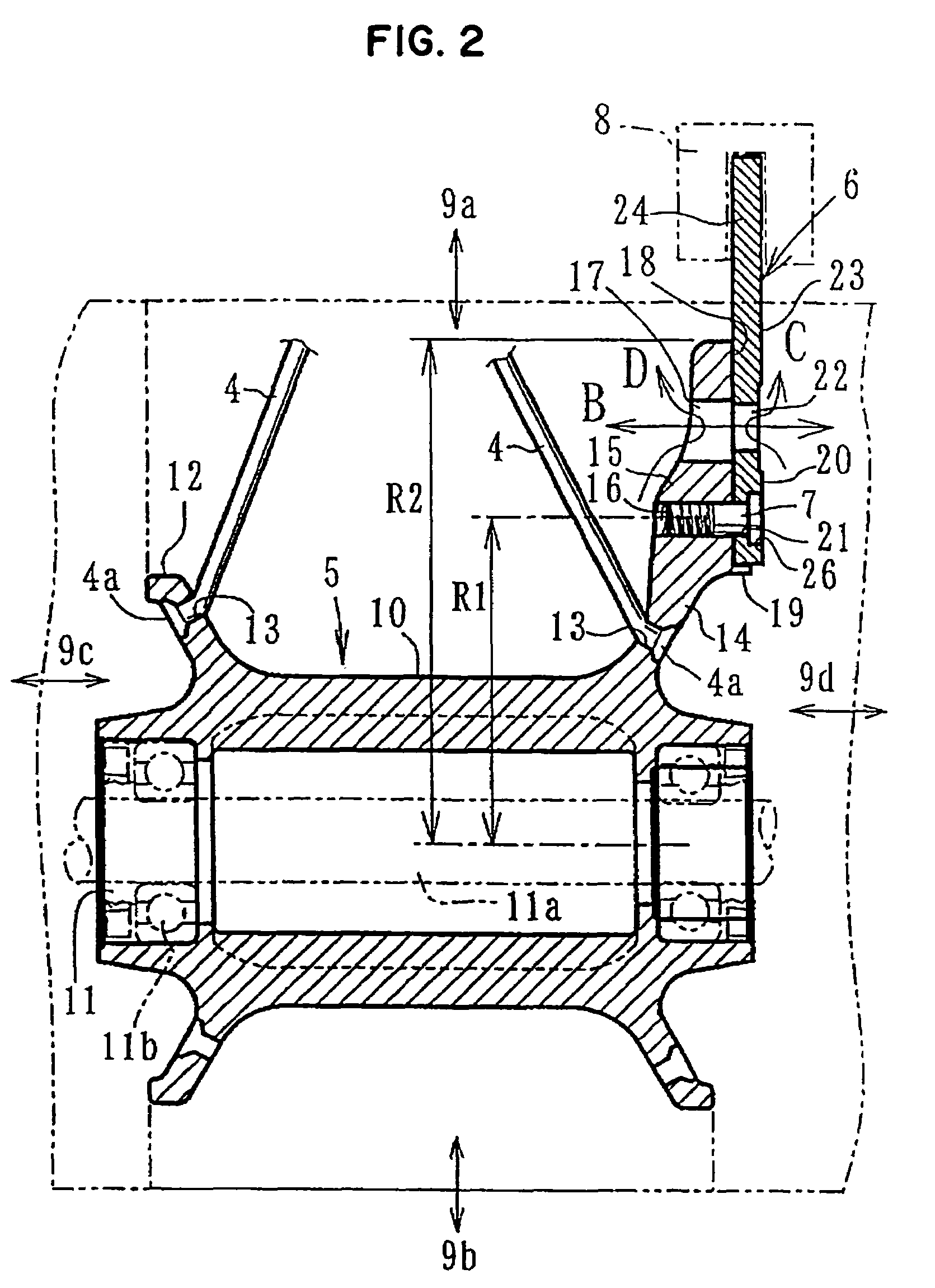
[0041]FIGS. 1 to 5 relate to a first embodiment applied to a spoke type wheel hub. FIG. 1 is a side view of a part of a front wheel. FIG. 2 is a cross-sectional view taken along line 2—2 of FIG. 1. FIG. 3 is a diagram showing a wheel hub part. FIG. 4 is a side view of a disc rotor. FIG. 5 is a cross-sectional view taken along line 5—5 of FIG. 4.
[0042]As shown in FIGS. 1 and 2, front wheel 1 includes tire 2, rim 3, spokes 4, and wheel hub 5. The inner circumference part of disc rotor 6 is superposed on one side surface of wheel hub 5 and is mounted integrally thereon by bolts 7. A brake caliper 8 is slidingly contacted on the outer circumference part of disc rotor 6.
[0043]As shown in FIGS. 3A, 3B, and 3C, wheel hub 5 of front wheel 1 is formed to be separated from rim 3 and spokes 4 and is molded by casting from suitable metal such as iron or light alloy. The material and molding method can be selected from any suitable choices. Its center part is provided with a cylindrical part 10 ...
second embodiment
[0053]Next, a second embodiment will be described with FIGS. 6 to 10. FIG. 6 is a side view of a part of a wheel. FIG. 7 is a cross-sectional view taken along line 7—7 of FIG. 6. FIG. 8 is a side view of a wheel. FIG. 9 is a cross-sectional view taken along line 9—9 of FIG. 8. FIG. 10 is a cross-sectional view enlarging a hub-side mounting part of FIG. 7. Common numerals are used for parts common to the above embodiment, and a description of the common parts is omitted.
[0054]This embodiment has an integral molding wheel 30 in which rim 31, spokes 32 and hub 33 are integrally cast. The material and the molding method in this case can be selected from any suitable choices. A mounting step part 34 forming a flat ring-like step part is formed on one side surface of the hub 33. A suitable number of female screw holes 35 provided at an equal pitch in the circumference direction are formed therein. The inner circumference part of a separate body mounting part 36 superposed on the mounting ...
fifth embodiment
[0068]FIGS. 14A and 14B depict a fifth embodiment in which parts corresponding to the hub-side recess parts 50 of FIG. 12 are formed as hub-side through-holes 45 extended therethrough. FIG. 14A of the drawing is shown together with FIG. 14B, which is a view taken along line 14B—14B of FIG. 14A. In this example, for convenience, a bolt 7 is provided on a concentric circle in which rotor side through-holes 22 are provided. As in FIGS. 12 and 13, it may be provided in a position on the inner circumference side from the range in which the rotor side through-holes 22 are provided.
PUM
 Abstract
Description
Claims
Application Information
 - R&D
- Intellectual Property
- Life Sciences
- Materials
- Tech Scout
- Unparalleled Data Quality
- Higher Quality Content
- 60% Fewer Hallucinations
Browse by: Latest US Patents, China's latest patents, Technical Efficacy Thesaurus, Application Domain, Technology Topic, Popular Technical Reports.
© 2025 PatSnap. All rights reserved.Legal|Privacy policy|Modern Slavery Act Transparency Statement|Sitemap|About US| Contact US: help@patsnap.com


