Debugging application performance over a network

Inactive Publication Date: 2006-02-09
RADWARE
View PDF11 Cites 147 Cited by
  • Summary
  • Abstract
  • Description
  • Claims
  • Application Information

AI Technical Summary

Benefits of technology

[0019] The current invention offers a solution to actively detect performance problems, locate the potential source of the problem and assist in fixing and bypassing the failure. The invention includes active networking equipment called application debugging switch and a central monitoring station called Debugging Center.

Problems solved by technology

Due to problems like failures and overloading, administrators are duplicating applications such that there is no single point of failure in the network and each application can scale over an unlimited number of resources.

Method used


Image

  • Debugging application performance over a network
  • Debugging application performance over a network
  • Debugging application performance over a network

Examples


Embodiment Construction

[0060] While this invention is illustrated and described in a preferred embodiment, the invention may be produced in many different configurations. There is depicted in the drawings, and will herein be described in detail, a preferred embodiment of the invention, with the understanding that the present disclosure is to be considered as an exemplification of the principles of the invention and the associated functional specifications for its construction and is not intended to limit the invention to the embodiment illustrated. Those skilled in the art will envision many other possible variations within the scope of the present invention.

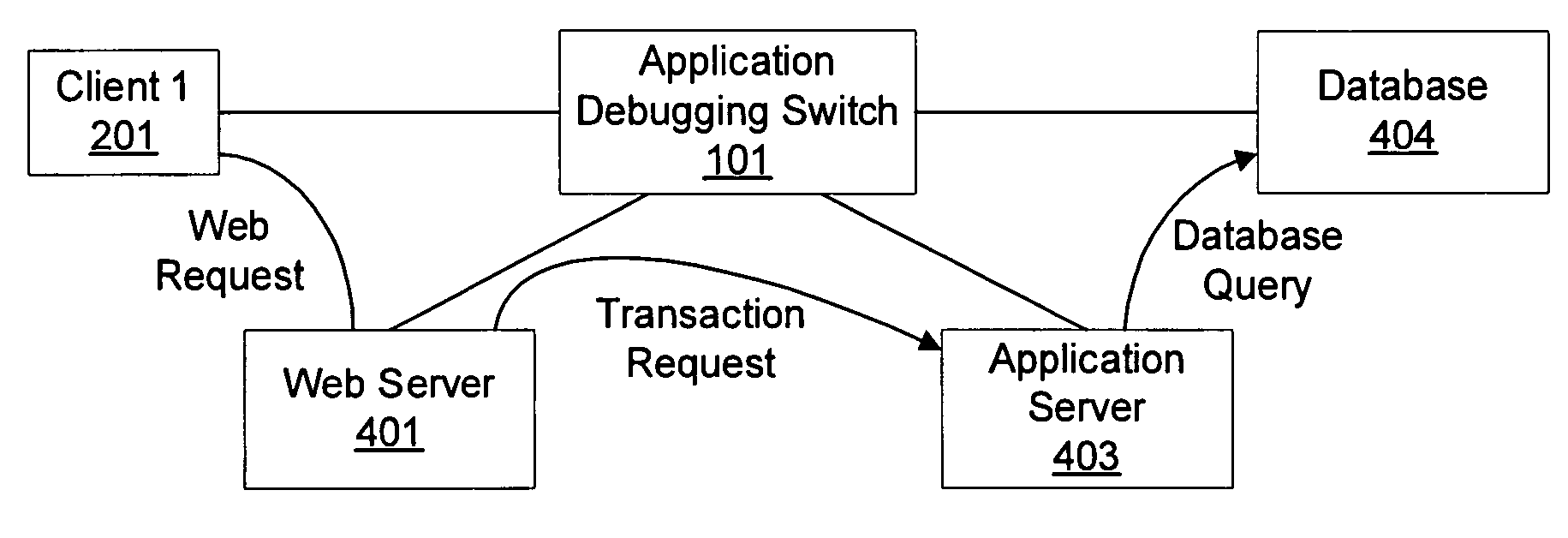
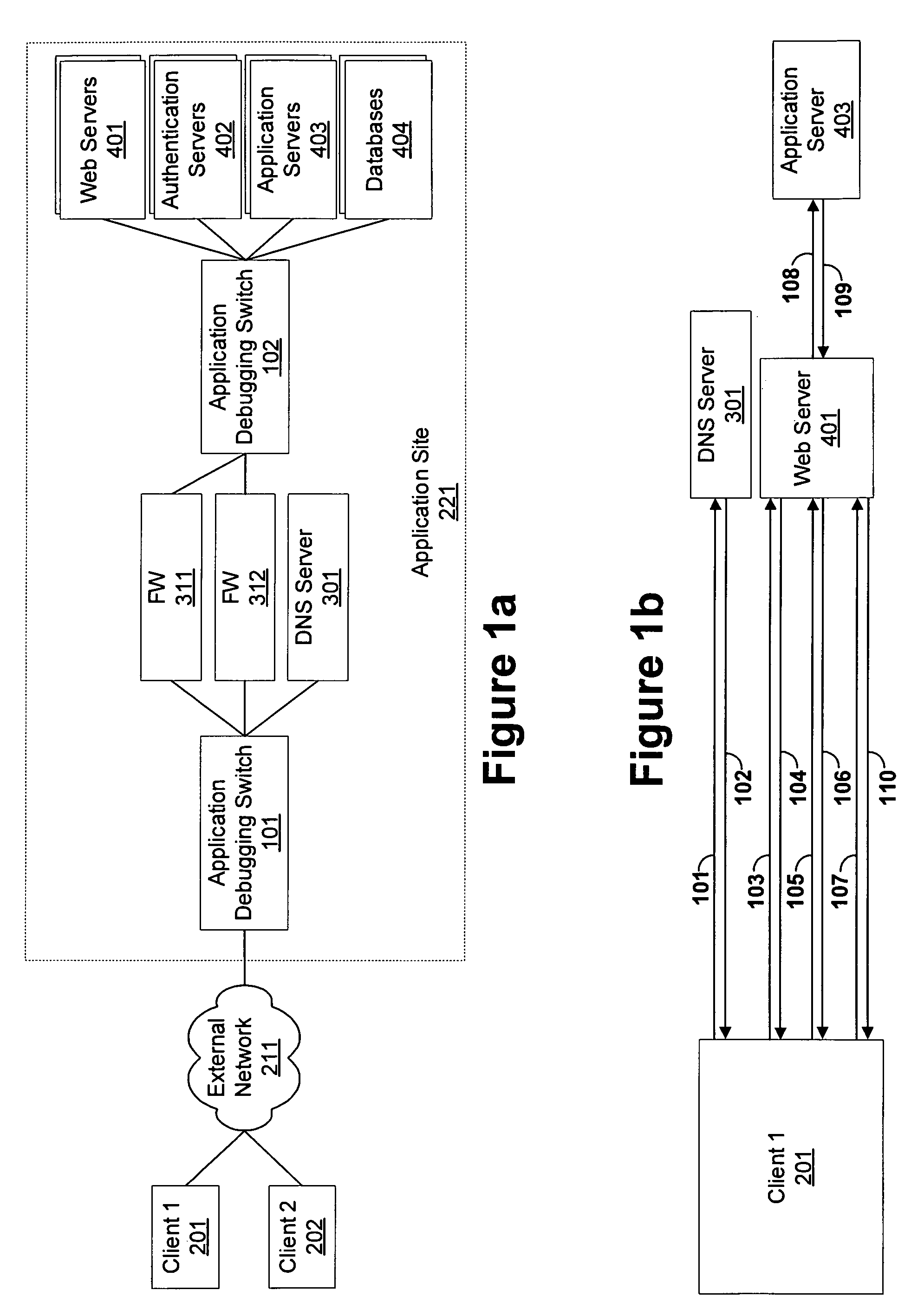
[0061]FIG. 1A describes an application environment according to the present invention. Clients 201 and 202 connect through external network 211 to application site 221. Application site 221 includes DNS server 301, security gateways 311 and 312, Web server cluster 401, authentication server cluster 402, application server cluster 403, and database 40...


PUM


Abstract

An application debugging switch also monitors application performance. The application debugging switch forwards the requests from a first host to a second host, and later forwards the response coming from that second host to that first host. As most of the applications work in a request—response architecture, the application debugging switch can measure the response time of the application. The switch attaches a timestamp to each request that it forwards. When the response to that request comes to the switch, the switch can determine the response time of that application. The application debugging switch collects multiple samples of response time over a certain period of time. These samples provide a good measurement for the average application response time. The response time is a combination of the network response time and the application response time. The application debugging switch holds multiple measurement classes. Each class defines different sources or destinations of traffic (IP addresses and networks) and different applications (TCP/UDP ports or content identifiers in the requests). Collecting the response time for each class separately allows zooming in to an application and user that experience bad service and detect the reason for their failure.

Description

PRIORITY INFORMATION [0001] This application claims the benefit of U.S. Provisional Application No. 60 / 584,253, filed Jun. 29, 2004, herein incorporated by reference.BACKGROUND OF THE INVENTION [0002] 1. Field of Invention [0003] The present invention relates generally to the field of monitoring computer networks. More specifically, the present invention is related to monitoring network response time and the application response time. [0004] 2. Discussion of Prior Art [0005] Computer networks today are growing fast and becoming the main media for communications inside organizations and between users world wide. Network speeds are also growing and the network today can serve more content (images, audio, video) in good quality. All in all, the network is currently evolving to be a platform for many services and applications—from the basic services of e-mail and browsing information on the network, through the online shopping and trading, until games, voice and video services. Each ser...

Claims


Application Information

Patent Timeline
Patent Type & Authority Applications(United States)
IPC IPC(8): H04Q7/00
CPCH04L43/022H04L69/16H04L43/106
Inventor PELES, AMIR
Owner RADWARE
Why Eureka
Try Eureka