

Phase-controlled current source for phase-locked loop
a current source and phase-locked loop technology, applied in the field of phase-locked loops, can solve the problems of too much surge, process cannot predict precisely the delay time, and cannot be applied in the high operation frequency field, so as to eliminate the parasitic effect, save power consumption of electrical circuits, and simplify electrical layou
- Summary
- Abstract
- Description
- Claims
- Application Information
AI Technical Summary
Benefits of technology
Problems solved by technology
Method used
Image

Examples
Embodiment Construction
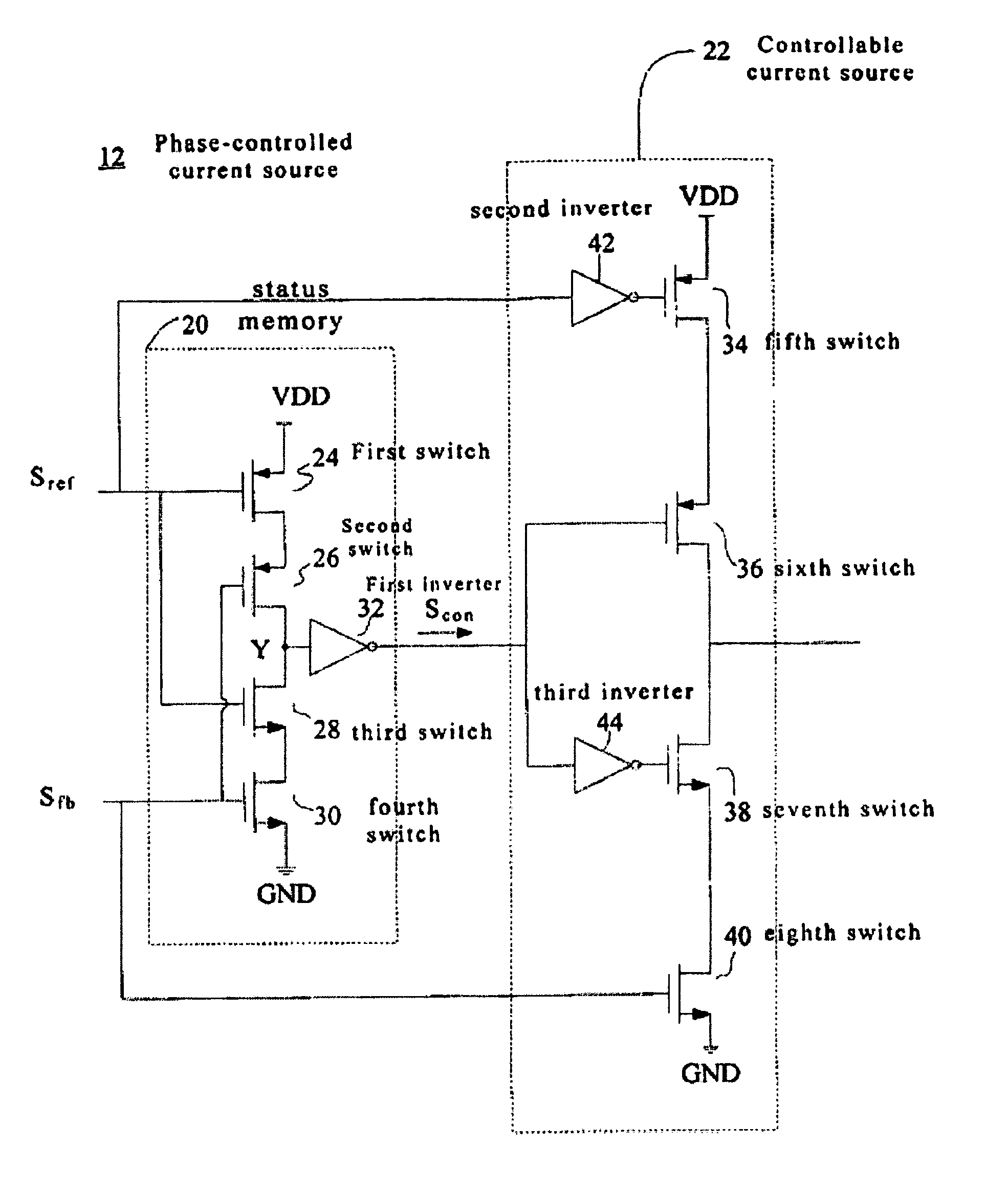
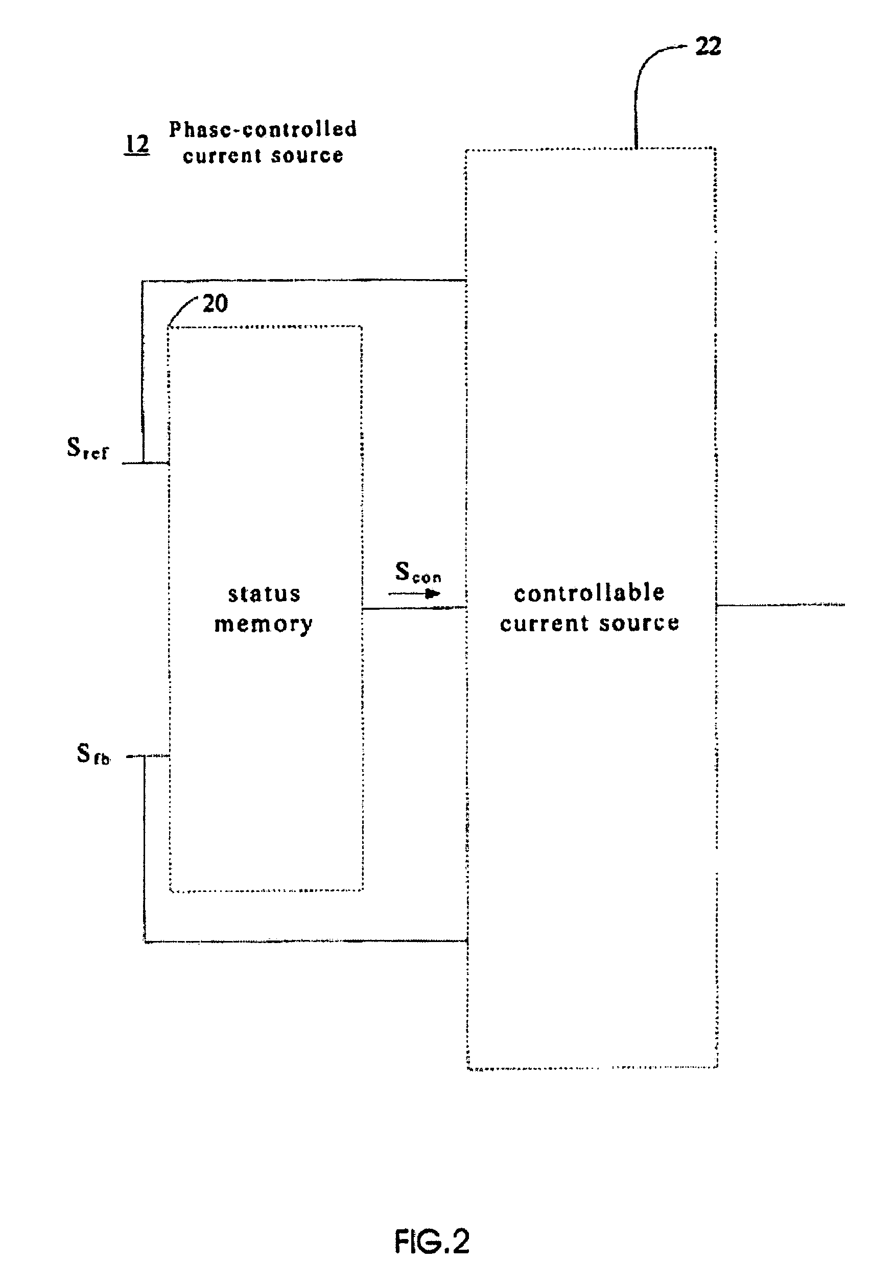
[0008]A phase-controlled current source for phase-locked loop is proposed in the current invention. The major difference between it and the conventional phase-locked loop is to design a phase frequency detector and charge pump function in the same structure, that is, phase-controlled current source, it has the characteristic of controlling the output charging and discharging current by phase. It is achieved through a status memory and a controllable current source serially connected to the high and low voltage side, therefore, the conventional detection dead zone issue of prior art phase-locked loop is eliminated. Additionally, since it has simple structure and no feedback mechanism is needed, it can thus be used in high frequency operation.
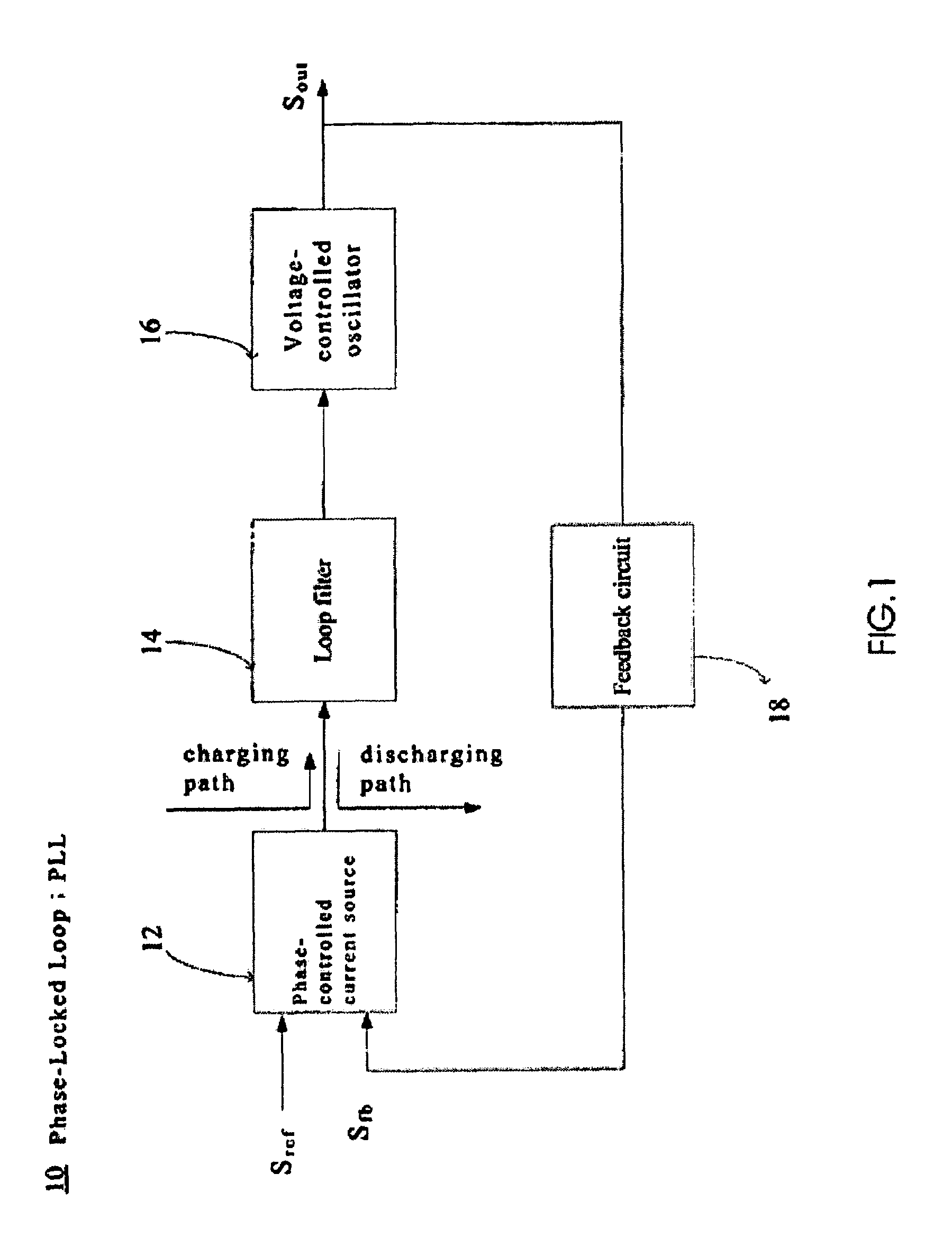
[0009]FIG. 1 shows an illustration of the basic structure of phase-locked loop 1 of the current invention. Phase-locked loop 10 comprises of a phase-controlled current source 12, a loop filter 14, a voltage-controlled oscillator 16 and a feedback...
PUM
 Abstract
Description
Claims
Application Information