Tunable external cavity laser diode using variable optical deflector
a laser diode and variable technology, applied in the direction of optical elements, semiconductor lasers, instruments, etc., can solve the problems of slow variable speed, large size, and degraded laser stability, and achieve high-speed tunability
- Summary
- Abstract
- Description
- Claims
- Application Information
AI Technical Summary
Benefits of technology
Problems solved by technology
Method used
Image

Examples
first embodiment
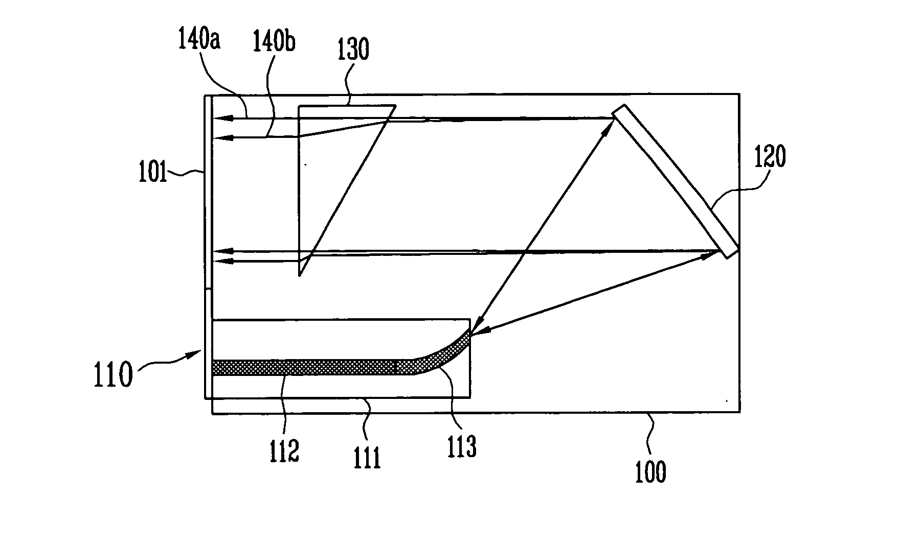
[0039]FIG. 3 is a structure diagram illustrating a tunable external cavity laser diode using a variable optical deflector according to the present invention.
[0040] A semiconductor optical amplifier 112, a concave diffraction grating 120, and a variable optical deflector 130 are integrated into an InP (or GaAs) based slab waveguide 100.
[0041] The InP (or GaAs) based slab waveguide 100, which is made of, for example, an InP (or GaAs) based semiconductor substrate, serves to guide a beam outputted from the semiconductor optical amplifier 112 and a passive waveguide 113 by spreading in parallel as well as by vertically confining the beam. In addition, a cross section of the InP (or GaAs) based slab waveguide 100 serves as a reflective mirror 101 reflecting the parallel beam diffracted by the diffraction grating 120.
[0042] The semiconductor optical amplifier 112, which is a medium having a gain of a light signal and is also a light source that generates beams of several wavelengths, ha...
second embodiment
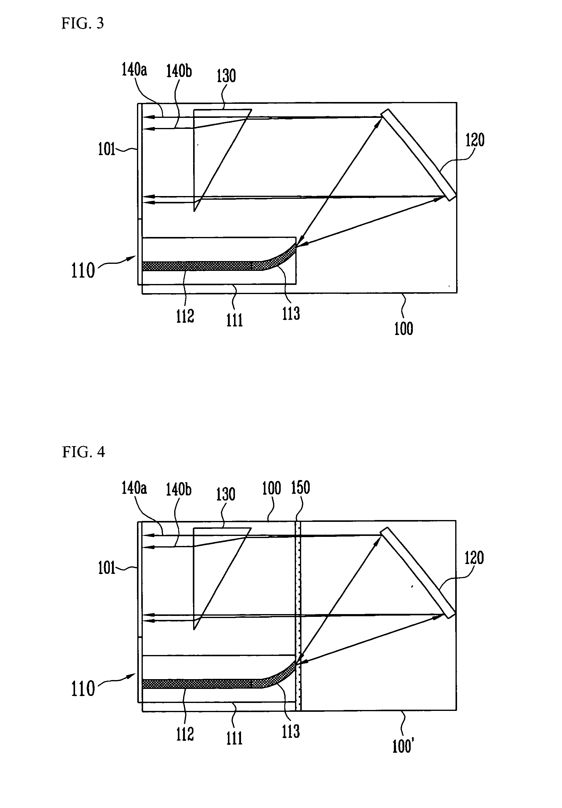
[0052]FIG. 4 is a structure diagram illustrating a tunable external cavity laser diode using a variable optical deflector according to the present invention, where like reference numerals refer to like elements shown in FIG. 3.
[0053] Basically, the tunable external cavity laser diode shown in FIG. 4 has the same configuration as that of FIG. 3. However, in the tunable external cavity laser diode of FIG. 3, the InP (or GaAs) based slab waveguide 100, the variable optical deflector 130, and the diffraction grating 120 are formed on the same substrate, while in the tunable external cavity laser diode of FIG. 4, the variable optical deflector 130 is formed in the InP (or GaAs) based slab waveguide 100, the concave diffraction grating 120 is formed in a silica (or polymer) based slab waveguide 100′, and these two slab waveguides are hybridly integrated to be connected to each other.
[0054] In addition, an antireflective thin film 150 is deposited at an interface between the two slab wave...
third embodiment
[0055]FIG. 5 is a structure diagram illustrating a tunable external cavity laser diode using a variable optical deflector according to the present invention, in which like reference numerals refer to like elements shown in FIG. 4.
[0056] In the tunable external cavity laser diode shown in FIG. 4, the InP (or GaAs) based slab waveguide 100 and the silica (or polymer) based slab waveguide 100′ are directly connected for optical coupling. However, in the present embodiment, the two slab waveguides 100 and 100′ are not directly connected but a cylindrical lens 160 is interposed between the two slab waveguides 100 and 100′ to enhance optical coupling efficiency. In the case where the two slab waveguides 100 and 100′ are directly connected, a design allowing the effective refractive index and a waveguide mode to be as close as possible is required to minimize an optical coupling loss. However, in the case where the two slab waveguides 100 and 100′ are optically connected using the cylindri...
PUM
 Abstract
Description
Claims
Application Information
 - R&D
- Intellectual Property
- Life Sciences
- Materials
- Tech Scout
- Unparalleled Data Quality
- Higher Quality Content
- 60% Fewer Hallucinations
Browse by: Latest US Patents, China's latest patents, Technical Efficacy Thesaurus, Application Domain, Technology Topic, Popular Technical Reports.
© 2025 PatSnap. All rights reserved.Legal|Privacy policy|Modern Slavery Act Transparency Statement|Sitemap|About US| Contact US: help@patsnap.com