
Method of manufacturing a semiconductor device with a strained channel

a manufacturing method and semiconductor technology, applied in the field of manufacturing semiconductor devices, can solve the problems of reducing the dielectric thickness of the gate, compromising device performance, and affecting the performance of the device, and achieve the effect of reducing the cost of manufacturing semiconductors

Active Publication Date: 2006-02-09
CHARTERED SEMICONDUCTOR MANUFACTURING
View PDF4 Cites 21 Cited by
  • Summary
  • Abstract
  • Description
  • Claims
  • Application Information

AI Technical Summary

Benefits of technology

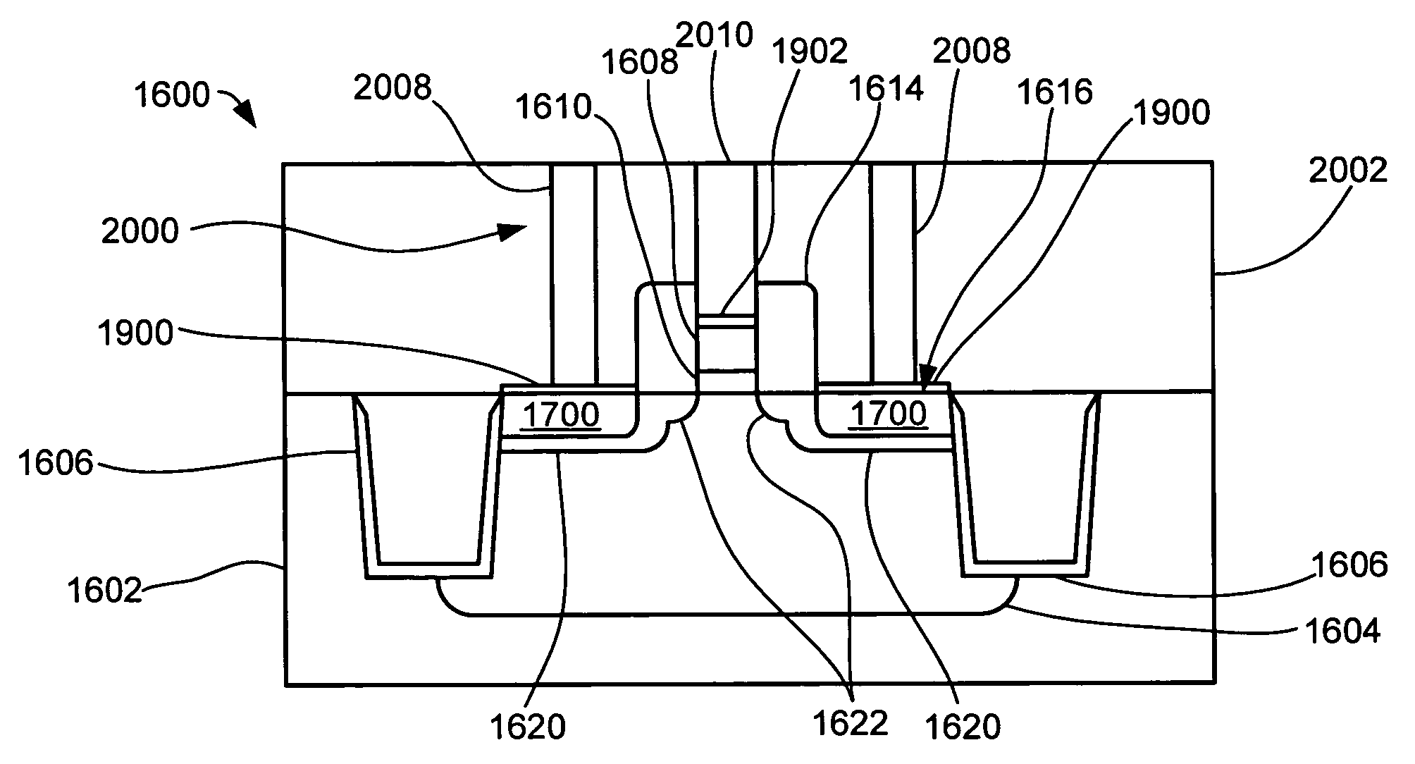
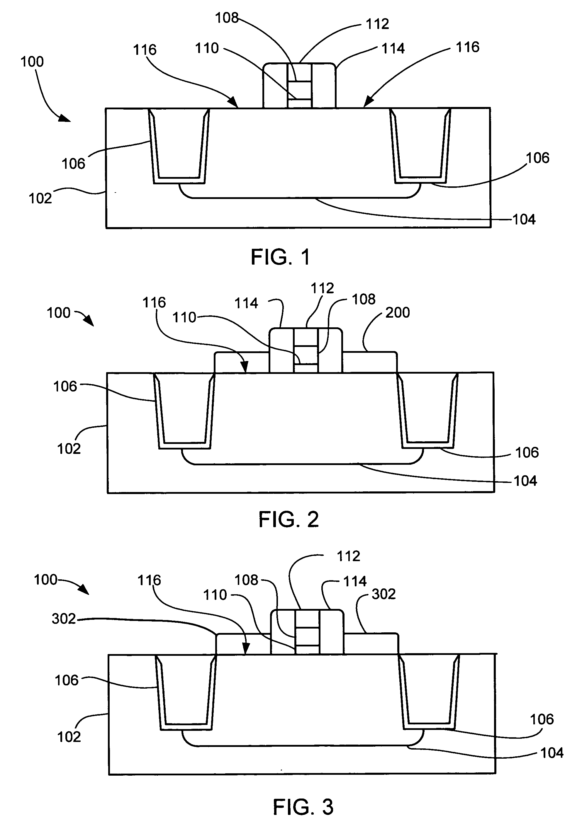
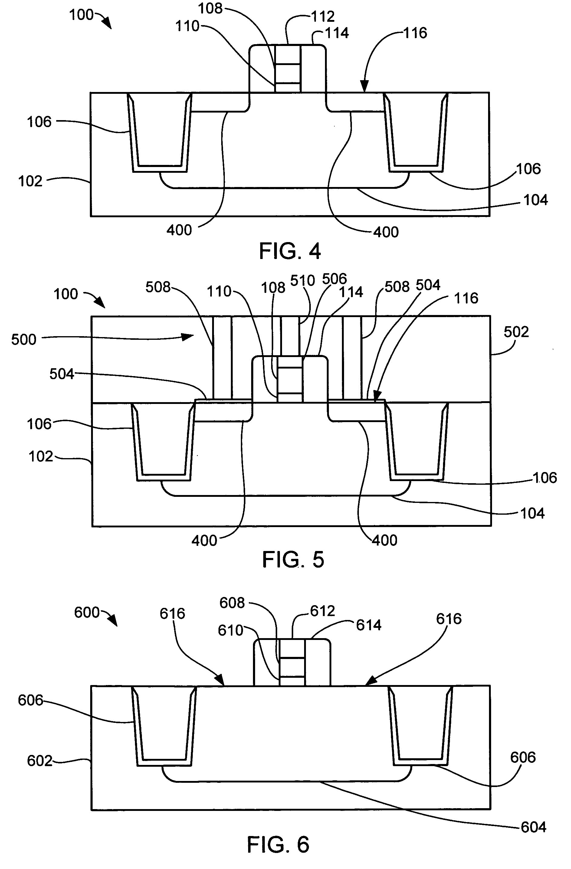
[0017] The present invention also avoids etching a recess in the area of the source / drain regions and depositing SiGe or silicon / germanium / carbon (SiGeC) in the recess to strain the channel of the transistor thereby eliminating the cost of manufacturing the semiconductors, introduced by the additional Si recess etch step.

Problems solved by technology

Semiconductor devices are made in and on wafers by extremely complex systems that require the coordination of hundreds or even thousands of precisely controlled processes to produce a finished semiconductor wafer.
However, reducing the gate dielectric thickness can compromise device performance because of the associated increase in gate leakage current.
However, these devices have the disadvantages of self-heating and a tight thermal budget window.
This method involves an additional etching step that adds to the cost of manufacturing the devices.
This approach requires an insulating layer that also adds to the cost of manufacturing the devices.
Solutions to these problems have been long sought but prior developments have not taught or suggested any solutions and, thus, solutions to these problems have long eluded those skilled in the art.

Method used


Image

  • Method of manufacturing a semiconductor device with a strained channel
  • Method of manufacturing a semiconductor device with a strained channel
  • Method of manufacturing a semiconductor device with a strained channel

Examples


Embodiment Construction

[0040] In the following description, numerous specific details are given to provide a thorough understanding of the invention. However, it will be apparent that the invention may be practiced without these specific details. In order to avoid obscuring the present invention, some well-known process steps are not disclosed in detail.

[0041] Additionally, the drawings showing embodiments of the present invention are semi-diagrammatic and not to scale and, particularly, some of the dimensions are for the clarity of presentation and are shown greatly exaggerated in the FIGs. Generally, the device can be operated in any orientation.

[0042] The term “horizontal” as used herein is defined as a plane parallel to the conventional plane or surface of the substrate, regardless of its orientation. The term “vertical” refers to a direction perpendicular to the horizontal as just defined. Terms, such as “on”, “above”, “below”, “bottom”, “top”, “side” (as in “sidewall”), “higher”, “lower”, “over”, ...


PUM


Abstract

A method of manufacturing a semiconductor device provides a semiconductor substrate with a gate and a number of source / drain regions on the semiconductor substrate. A layer containing a strain-inducing element is provided over the number of source / drain regions. The strain-inducing element is driven from the layer containing a strain-inducing element into the number of source / drain regions. A number of source / drains is formed in the number of source / drain regions.

Description

CROSS-REFERENCE TO RELATED APPLICATION(S) [0001] This application claims the benefit of U.S. Provisional Patent Application Ser. No. 60 / 599,650 filed Aug. 5, 2004, and the subject matter thereof is hereby incorporated herein by reference thereto.TECHNICAL FIELD [0002] The present invention relates generally to manufacturing semiconductors, and more particularly to manufacturing semiconductors having a strained channel. BACKGROUND ART [0003] Electronic products are used in almost every aspect of life, and the heart of these electronic products is the semiconductor, or integrated circuit. Semiconductor devices are used in everything from airplanes and televisions to wristwatches. [0004] Semiconductor devices are made in and on wafers by extremely complex systems that require the coordination of hundreds or even thousands of precisely controlled processes to produce a finished semiconductor wafer. Each finished semiconductor wafer has hundreds to tens of thousands of semiconductor dies...

Claims


Application Information

Patent Timeline
Patent Type & Authority Applications(United States)
IPC IPC(8): H01L21/8234
CPCH01L21/823807H01L29/7843H01L29/7833H01L29/66628
Inventor CHUI, KING JIENSAMUDRA, GANESHYEO, YEE CHIALIU, JINPINGTEE, KHENG CHOKPHUA, WEE HONGWONG, LYDIA
Owner CHARTERED SEMICONDUCTOR MANUFACTURING
Learn More