Phosphorescent power conducting device

a technology of power conducting device and phosphorescent light, which is applied in the direction of wave amplification device, line/current collector details, electrical apparatus, etc., can solve the problems of physical damage to the powered device, more abuse of the extension cord than the power cord, and injury to individuals, so as to reduce the lighting area, reduce the danger of moving or working around the extension cord, and reduce the effect of lighting area

Inactive Publication Date: 2006-02-16
AUTAC
View PDF4 Cites 2 Cited by
  • Summary
  • Abstract
  • Description
  • Claims
  • Application Information

AI Technical Summary

Benefits of technology

[0006] The present invention relates to a cord for supplying power to a powered device, the cord being made from a material that emits light also interchangeably referenced to herein as a “glow-in-the-dark feature”). By glowing in the dark the power cord provides a visual indicator of its location in reduced lighting areas. Such cords can be used in applications including, but not limited to, telephone and other communication cables, network patch cables, audio visual cables, lamps, clocks and other home appliance cords, optical cables, printer cables, Universal Serial Bus (USB) cables, computer and keyboard cables, power cables, medical and dental industries and video / monitor cables. The glow-in-the-dark features of the power cords make moving or working around the cords safer in reduced lighting areas.

Problems solved by technology

However, extension cords are also more abused than power cords, in that they are often distanced from the powered device.
Further, extension cords are currently manufactured in such a manner that they cannot be easily seen in the dark, which leads to the cords becoming tripping hazards, which can result in injury to individuals, electrical accidents, and physical damage to powered devices.

Method used


Image

  • Phosphorescent power conducting device
  • Phosphorescent power conducting device
  • Phosphorescent power conducting device

Examples


Embodiment Construction

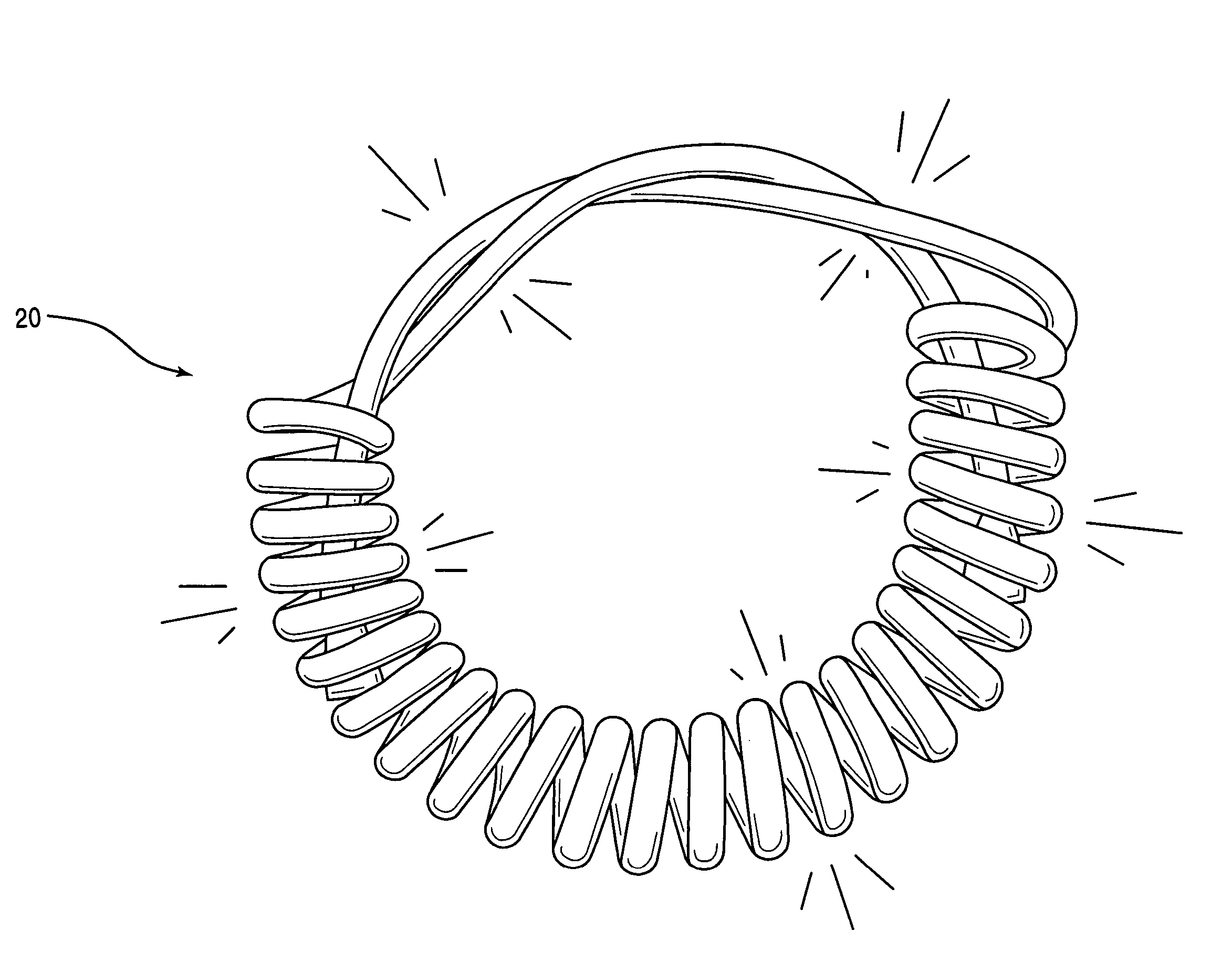
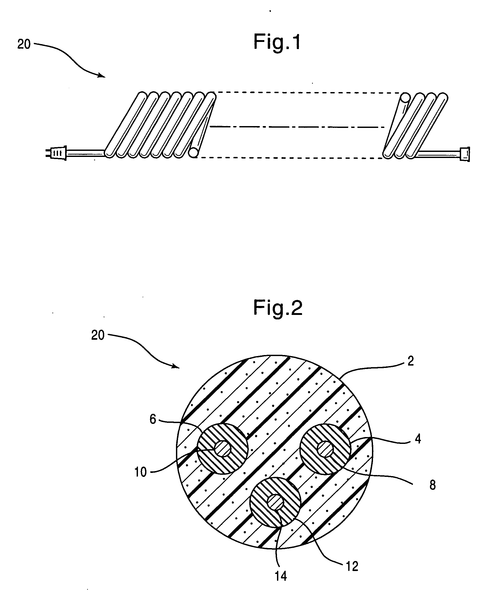
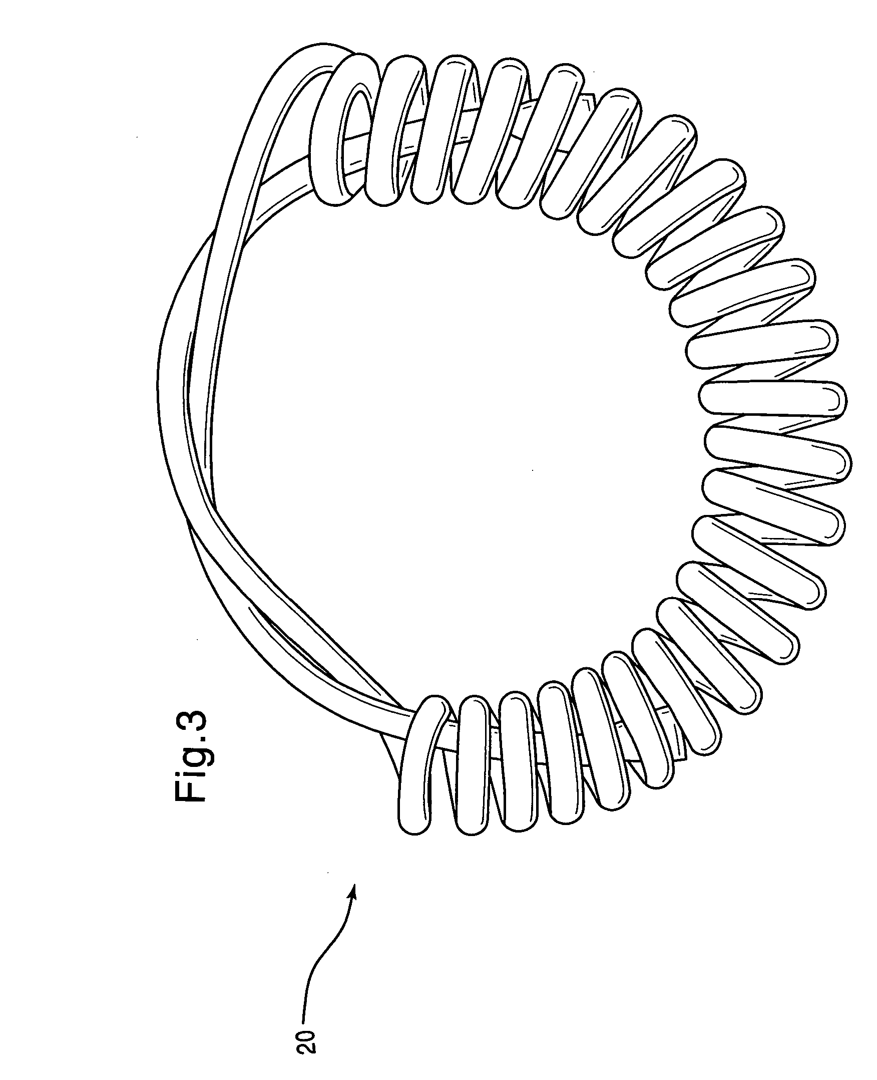
[0016] The present invention is directed to power cords that have phosphorescent capabilities. The cords can be power cords having a plug portion that connects an electrical device to an outlet, as shown for example, in FIG. 1. As shown in the cross-sectional view of FIG. 2, the cord can be a standard power cord 20, having a pair of wires 8, 10 for conducting electricity and a grounding wire 14 encased in insulating materials 4, 6, 12, respectively, such as Polyvinyl Chloride (PVC) or polypropylene. The power cord 20 can be encased in a conductor jacket 2 having phosphorescent properties. It is to be understood that the cord can be any cord or conduit for the conduction of power. In some embodiments, the conductor jacket is flame retardant.

[0017] The glow-in-the-dark feature can enhance safety in the workplace because the power cord 20 is more visible in reduced lighting areas than cords that do not emit light. The glow-in-the-dark feature can also be for decorative purposes, as a ...


PUM

PropertyMeasurementUnit
temperatureaaaaaaaaaa

Abstract

A phosphorescent power conducting device including an electricity conductor covered with a glow-in-the-dark jacket. The jacket is formed from a resinous material mixed with a color concentrate. The jacket glows after exposure to light so as to increase visibility of the conducting device.

Description

BACKGROUND OF THE INVENTION [0001] 1. Field of the Invention [0002] This invention relates to a power conducting device. More specifically, the present invention relates to a power cord that provides a visible indicator of its location in reduced lighting areas. [0003] 2. Description of the Related Art [0004] Many power cords are provided that blend in with or complement the electrical devices to which they conduct power from an outlet. An extension cord can also be used to connect the power cord of a powered electrical device to an outlet. Extension cords are regularly used in all aspects of electricity conducting. However, extension cords are also more abused than power cords, in that they are often distanced from the powered device. More often than not, extension cords are pulled, twisted, tied and taped, and used in a variety of conditions that are different from how a power cord directly attached to the powered device would be used. As a result, a person's mental connection bet...

Claims


Application Information

Patent Timeline
Patent Type & Authority Applications(United States)
IPC IPC(8): H01S4/00
CPCC09D5/22Y10T29/49002Y10T29/49117Y10T29/5187
Inventor BURKLE, MARIE L.
Owner AUTAC
Why Eureka
Try Eureka