Method of making cascaded multilayer stator winding with interleaved transitions

Active Publication Date: 2006-02-16
BORGWARNER INC
View PDF90 Cites 43 Cited by
  • Summary
  • Abstract
  • Description
  • Claims
  • Application Information

AI Technical Summary

Problems solved by technology

Such wire can be laced into the stator core winding slots in a very densely packed configuration, thereby improving “slot space utilization.” However, square- or rectangular-cross-section wire is more difficult to form and wind into the stator winding slots, since it is necessary to align the conductor cross-section with the slot.
Designers of stator assemblies further attempt to reduce or eliminate the need for providing electrical conductor terminations and connections in the stator assembly, as a need to physically connect conductors in the stator core assembly adversely impacts cost and complexity of the manufacturing process.
Such transitions presen

Method used


Image

  • Method of making cascaded multilayer stator winding with interleaved transitions
  • Method of making cascaded multilayer stator winding with interleaved transitions
  • Method of making cascaded multilayer stator winding with interleaved transitions

Examples


Embodiment Construction

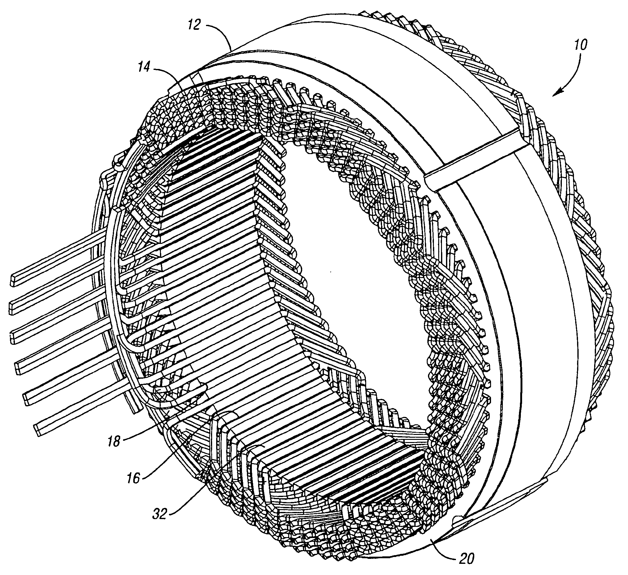
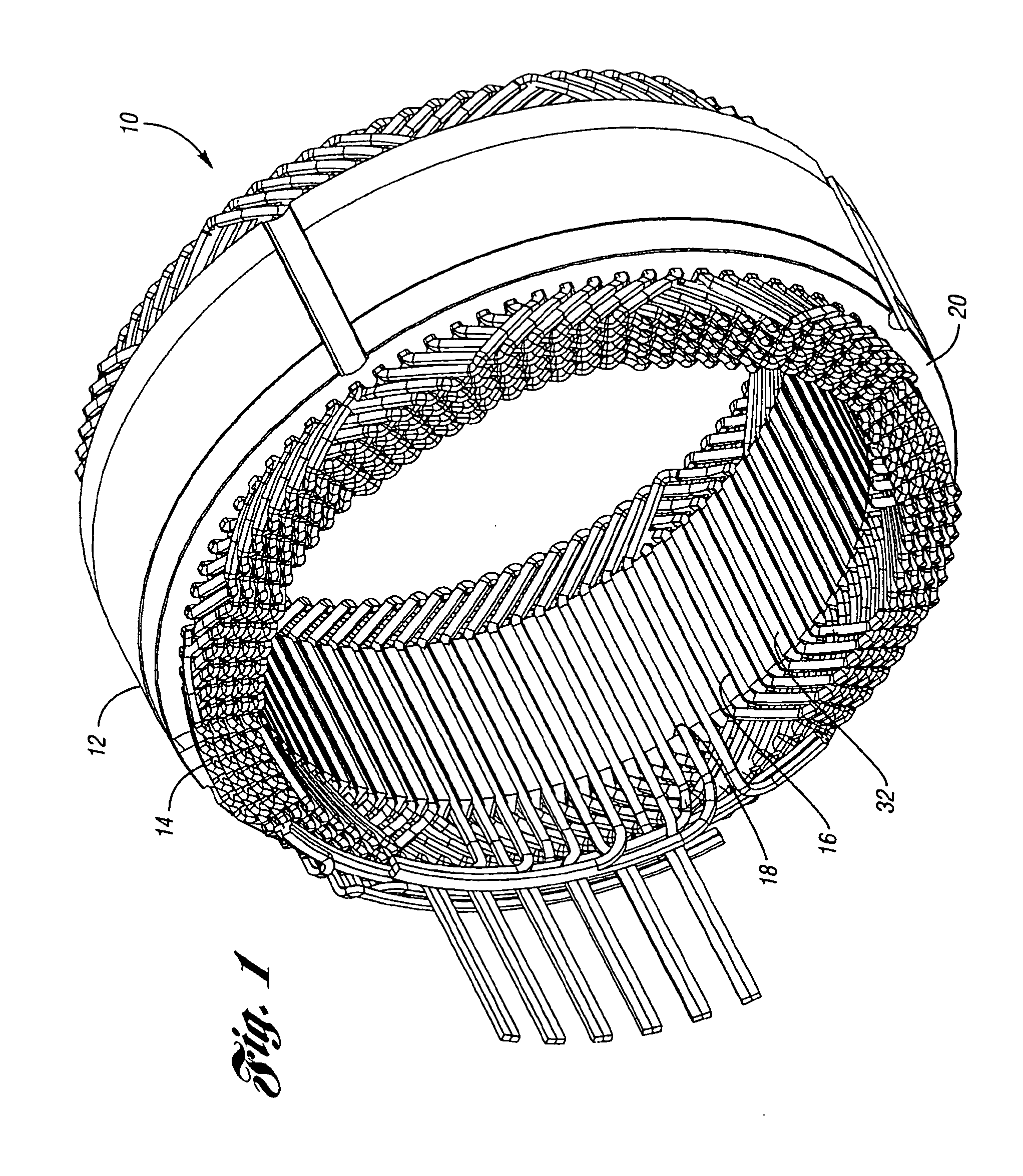
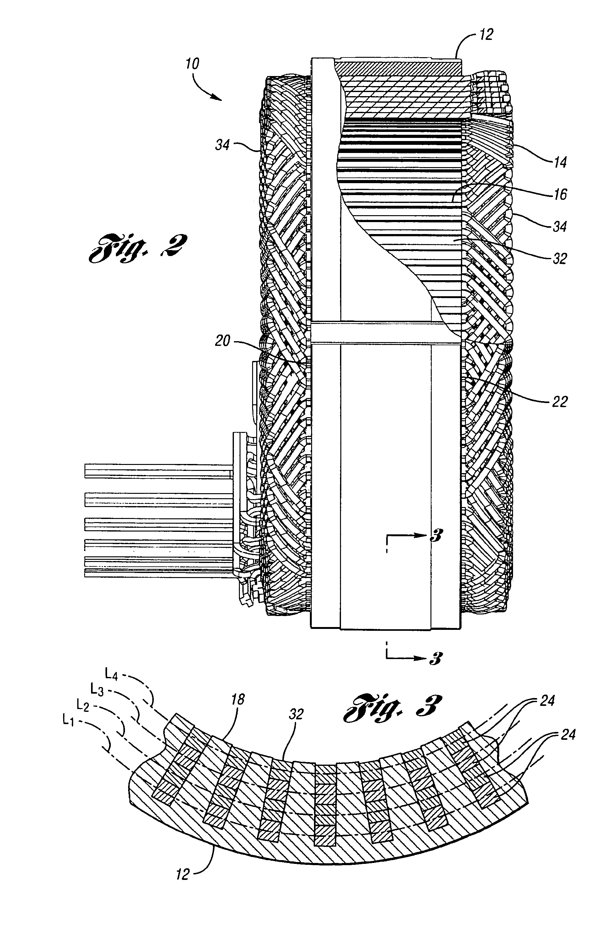
[0025] Referring to FIGS. 1-3, an exemplary twelve-conductor, six-phase, eight-layer stator 10 for a dynamoelectric machine, such as an alternator for a motor vehicle (not shown), includes a generally cylindrical stator core 12 and a stator winding 14 disposed in stator slots 16 defined about the inner periphery 18 of the stator core 12. The slots 16 are equidistantly and circumferentially spaced around the core's inner periphery 18, and extend axially through the stator core 12 from one axial end 20 of the core 12 to the other axial end 22 of the core 12.

[0026] The stator winding 14 is generally comprised of a plurality of conductors 24 wound around the stator core 12 within the stator slots 16 to thereby define several concentric conductor winding layers L. As seen in FIG. 3 (in which only four separate single-conductor winding layers L are illustrated for clarity), in order to achieve a high slot fill, the conductor 24 may be of square or rectangular shape when viewed in cross-s...


PUM

PropertyMeasurementUnit
Angleaaaaaaaaaa
Electrical conductoraaaaaaaaaa

Abstract

A method for making a stator assembly includes forming several continuous conductors with generally-coplanar parallel-spaced straight segments interconnected by end loop segments, as by winding each of several conductors on a peg board, and then pressing the conductors to form either one, two, or three generally-orthogonal “jogs” in a given end loop segment. The conductors are interpositioned with their straight segments staggered and with a first leg of each subsequent conductor's end loop segments generally overlying a second leg of the immediately-prior conductor's end loop segments, except for the two end loop segments following the first conductor's “nth” straight segment, and multiples thereof, where the stacking order is reversed (“n” being equal to the number of stator core slots divided by the number of conductors that will form a given winding layer). The resulting preform is inserted into the core slots over multiple revolutions to thereby obtain a multilayer cascaded stator winding with interleaved transitions.

Description

FIELD OF THE INVENTION [0001] The invention relates to cascaded stator winding configurations for dynamoelectric machines, such as an automotive electrical alternator, and methods for making such stator winding configurations using a plurality of continuous conductors. BACKGROUND OF THE INVENTION [0002] Electrical alternators adapted for use in motor vehicle applications typically include a rotor assembly rotatable within an annular stator. Rotor pole pieces, which may preferably be of an interleaved “claw pole” design, rotate with the rotor shaft, while the stator itself includes a stator core defining radially-extending slots in which a plurality of stator windings are disposed. An excitation winding is carried within the cavity formed between pole pieces of the rotor, and a DC signal is applied to the excitation winding through a pair of slip rings and associated brushes. The magnetic field produced by the winding interacts with the pole pieces to create an alternating polarity m...

Claims


Application Information

Patent Timeline
IPC IPC(8): H02K15/14H02K15/16
CPCH02K3/12H02K15/0435Y10T29/49071Y10T29/49009Y10T29/49012H02K15/0478
Inventor NEET, KIRK E.
Owner BORGWARNER INC
Why Eureka
Try Eureka