Method and system for controlling railroad surfacing

a technology for railroads and surfacing, applied in the direction of roads, measuring devices, construction, etc., can solve the problems of poor resurfacing accuracy, built-in error in rail correction, and difficult use of existing shadowboard systems, etc., to improve resurfacing accuracy and efficiency.

Inactive Publication Date: 2006-02-16
FABRICATION TECH ASSOC INC
View PDF13 Cites 40 Cited by
  • Summary
  • Abstract
  • Description
  • Claims
  • Application Information

AI Technical Summary

Benefits of technology

[0011] The present invention resides in a railroad rail surfacing control system, which can be used in combination with existing shadowboard systems. The system and method of the present invention improves resurfacing accuracy and efficiency such that the rails can be set within the necessary tolerances in automatic fashion in as few as a single pass. Thus, many more feet per day can be surfaced than using existing technology. Moreover, the method and system of the present invention allows vertical and horizontal curves to be automatically resurfaced.

Problems solved by technology

However, the current method of “tamper” or surfacing the rails and railroad ties using the existing shadowboard system leaves much to be desired.
The existing shadowboard system is also very difficult to use when the rail has vertical or horizontal curves or dips.
As the buggies with the projectors are typically between 50 and 100 feet in front of the tamper machine, there is a built-in error in the correction to the rails.
As such, only approximately 800 feet per day can be surfaced using the existing shadowboard system and tamper machines.
Moreover, the existing shadowboard systems are not extremely accurate and thus make the surfacing or tampering of commuter rail lines, which have much tighter tolerances, very time consuming and costly.

Method used


Image

  • Method and system for controlling railroad surfacing
  • Method and system for controlling railroad surfacing
  • Method and system for controlling railroad surfacing

Examples


Embodiment Construction

[0028] As shown in the accompanying drawings, for purpose of illustration, the present invention resides in a system and method for controlling railroad surfacing. As will be more fully discussed herein, the system and methodology of the present invention enable the automatic adjustment of the rails of the railroad track with little or no operator intervention. Proper railroad surfacing can be achieved in as little as one pass by a tamper machine by as few as a single worker. Moreover, as will be more fully discussed herein, the length of railroad track which can be adjusted and resurfaced per day is greatly increased in comparison to existing methods.

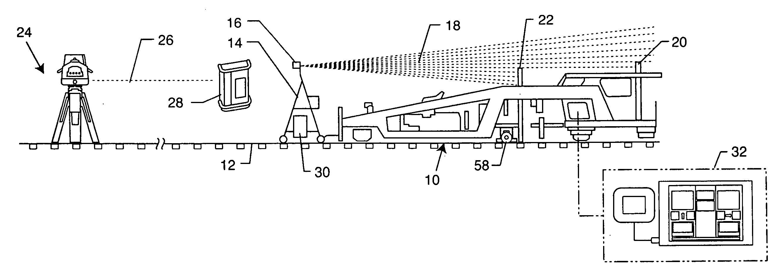
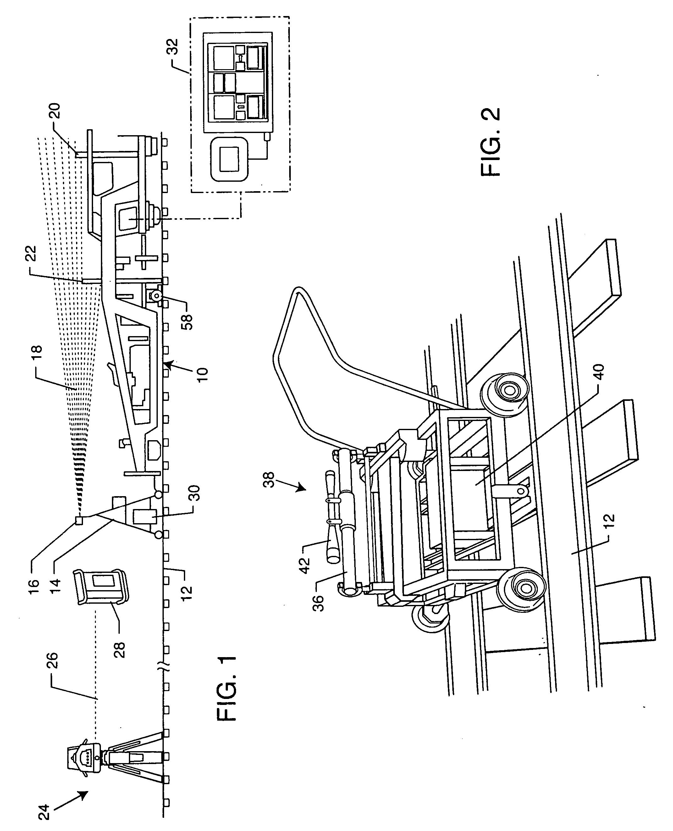
[0029] With reference now to FIG. 1, as discussed above, existing railroad surfacing systems include a tamper machine 10 which is capable of lifting and moving the rails 12 of a railroad track vertically and horizontally, and vibrating existing gravel or adding new gravel to properly raise and align the rails 12 to within accepted tol...


PUM


Abstract

A system and method for controlling railroad surfacing is provided. A computerized controller compares desired railroad rail position values with actual railroad rail position values such that a tamper machine raises, lowers, and horizontally moves the rails to correct the alignment of the rails and ties. The system may be used in conjunction with existing shadowboard tamper systems, with the computerized controller receiving precision reference signals corresponding to desired rail position values, and moving projectors according to the difference of the railroad rail position value and desired railroad position value.

Description

RELATED APPLICATION [0001] This application claims priority to U.S. Provisional Application Ser. No. 60 / 602,078, filed on Aug. 16, 2004.BACKGROUND OF THE INVENTION [0002] The present invention generally relates to railroad placement and surfacing. More particularly, the present invention relates to a method and system for controlling such railroad surfacing. The control system of the present invention can be used in conjunction with existing surfacing systems. [0003] When constructing a railroad, after properly grading the underlying land, a bed of gravel or ballast is formed from anywhere between one and three feet thick. The railroad ties are embedded in the ballast and the rails attached thereto. In the case of wooden railroad ties, the rails are nailed to the ties with spikes. In the case of concrete ties, clips connect the rails and the ties. [0004] The rails and ties must then be set at a predetermined height and alignment. The rails must be a certain height above the ballast ...

Claims


Application Information

Patent Timeline
Patent Type & Authority Applications(United States)
IPC IPC(8): E01B29/04
CPCE01B35/08E01B27/16
Inventor TOMASELLO, JEROME R.TOMASELLO, JAMES V.
Owner FABRICATION TECH ASSOC INC
Why Eureka
Try Eureka