Stream down type ice making machine

Inactive Publication Date: 2006-02-16
HOSHIZAKI ELECTRIC CO LTD
View PDF6 Cites 5 Cited by
  • Summary
  • Abstract
  • Description
  • Claims
  • Application Information

AI Technical Summary

Benefits of technology

[0006] The projecting height from the ice making face of the protrusion needs to be such an adequate size that the lump of ice having run over the protrusion will not be caught by the lump of ice of the downside. Namely, if the projecting height is inadequate, the lump of ice will be caught by the lump of ice of the downside, so that it will not fall promptly, thereby causing such problems as that the deicing time becomes long to decrease the daily ice making capacity, that the amount of lump of ice melting wastefully on the ice making face increases thereby to decrease the daily ice making capacity and to produce ice of abnormal shape, and that the power consumption and the amount of consumed water increase.
[0008] Namely, the present invention has been proposed, in view of the problem inherent in the conventional art described above, to resolve this suitably, and is intended to provide a stream down type ice making machine capable of facilitating falling of lumps of ice without producing distortion and the like in the ice making face.

Problems solved by technology

Namely, if the projecting height is inadequate, the lump of ice will be caught by the lump of ice of the downside, so that it will not fall promptly, thereby causing such problems as that the deicing time becomes long to decrease the daily ice making capacity, that the amount of lump of ice melting wastefully on the ice making face increases thereby to decrease the daily ice making capacity and to produce ice of abnormal shape, and that the power consumption and the amount of consumed water increase.
However, if high protrusions are molded in the ice making face by press work, distortion and the like are produced in the ice making face, thereby causing a problem affecting the ice making capacity.

Method used


Image

  • Stream down type ice making machine
  • Stream down type ice making machine
  • Stream down type ice making machine

Examples


first embodiment

Modification of First Embodiment

[0024] The shape of the protrusion is not limited to a triangle, but may be a shape in which at least an upper face thereof is inclined downward, and, for example, as shown in FIG. 4, it may be a straight one downwardly inclined toward the outside direction (the side being away from the ice making face 12a) from the bended edge between the ice making face 12a and the extension portion 16a. Then, also in a protrusion 20 having a straight line shape, the lump of ice C can be caused to be away from the ice making face 12a along a slope 20a thereof. In addition, while the projecting dimensions from the extension portion 16a of the protrusion 20 are suppressed to be small, the position at the tip (the lower end of the slope) can be separated from the ice making face 12a sufficiently, thereby allowing the lump of ice C to fall promptly.

[0025] Although in the first embodiment the protrusions are provided opposite to the extension portions (the vertical ribs...

second embodiment

[0026]FIG. 5 shows an ice making portion of a stream down type ice making machine according to the second embodiment. In addition, concerning the same members as those of the first embodiment described above, the same numerals are given and the detailed description thereof will be omitted.

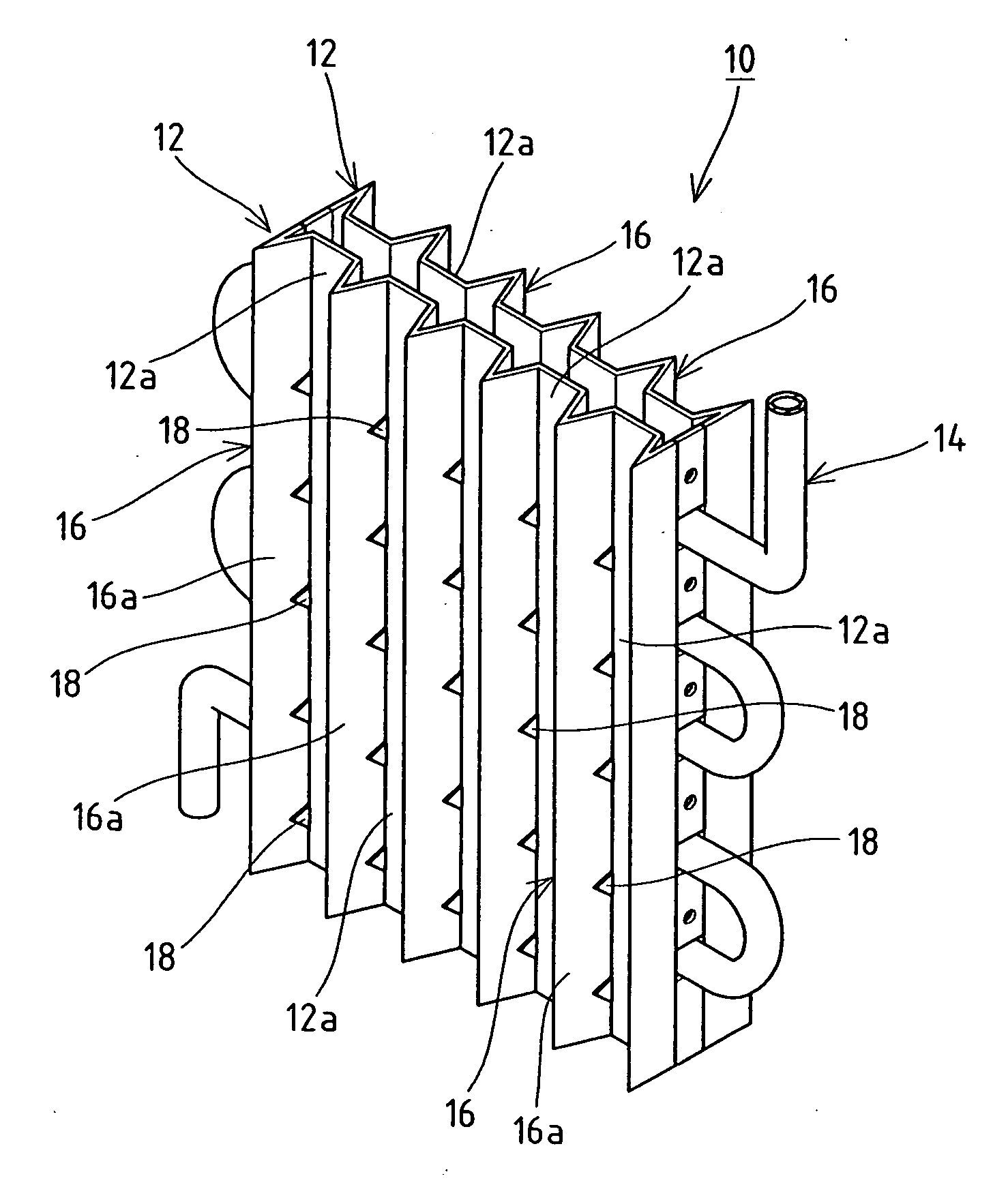
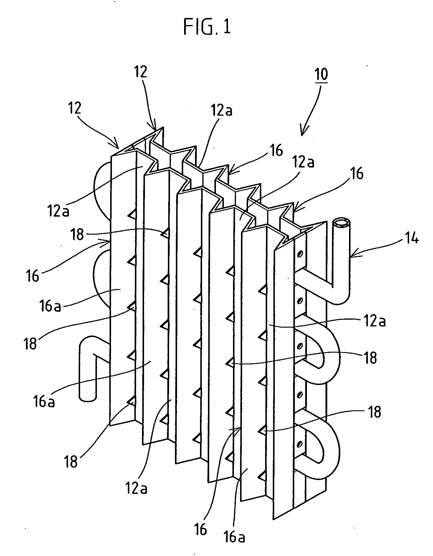
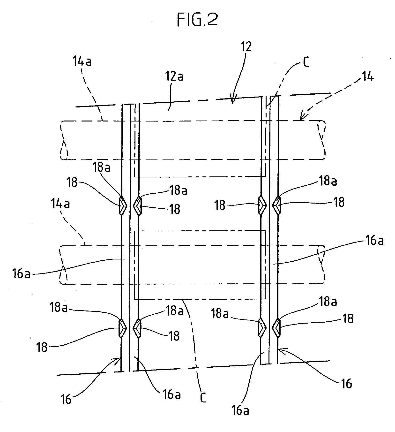
[0027] In an ice making portion 22 according to the second embodiment, the protrusion 18 formed in each extension portion 16a in the vertical rib 16 provided in the ice making plate 12 is set in the position corresponding to the evaporator 14 arranged in the back face of the ice making plate 12. Namely, in the ice making process, in the ice making portion 22 of the second embodiment, the protrusions 18 and 18 are included by the lump of ice C produced in the ice making region. Then, moving to the deicing process, where a hot gas is cyclically supplied to the evaporator 14 and a deicing-water is supplied to the back face of the ice making plate 12, and when the frozen portion between the ice making...


PUM


Abstract

A stream down type ice making machine having an ice making plate in which an ice making region is defined between a pair of vertical ribs, the pair of vertical ribs being spaced apart in the width direction and projecting from an ice making face and an evaporator disposed meanderingly in the back face opposite to the ice making face of the ice making plate, the ice making region of the ice making plate is cooled by cyclically supplying the evaporator with a refrigerant as well as ice-making water is supplied to flow down thereon so that many a lump of ice is produced on the ice making region, wherein protrusions projecting to the ice making region side and having a slope formed on the upper face thereof, the slope being inclined from above to down as being away from the ice making face, are provided in the vertical rib.

Description

BACKGROUND OF THE INVENTION [0001] 1. Technical Field [0002] This invention relates to a stream down type ice making machine that produces lumps of ice in an ice making region by flow-supplying an ice-making water in the ice making region of an ice making plate in which an evaporator is arranged in the back face thereof. [0003] 2. Description of the Related Art [0004] As the ice making machine for producing lumps of ice continuously, there is known a stream down type ice making machine, wherein a pair of ice making plates are arranged vertically opposite to an evaporator being sandwiched therebetween, the evaporator constituting a freezing system, and an ice-making water is spray-supplied onto the surface (the ice making face) of each of the ice making plates to be cooled with refrigerant, the refrigerant being cyclically supplied to the evaporator, thereby forming a lump of ice, and then the obtained lump of ice is peeled off to be discharged by falling. [0005] In the deicing opera...

Claims


Application Information

Patent Timeline
IPC IPC(8): F25C1/22F25C1/00
CPCF25C1/12F25C2400/02F25C5/10F25C1/22
Inventor SANUKI, MASAOTOYA, CHIYOSHIWAKATSUKI, YUJI
Owner HOSHIZAKI ELECTRIC CO LTD
Why Eureka
Try Eureka