Vapor compression system

Active Publication Date: 2013-08-20
JOHNSON CONTROLS TYCO IP HLDG LLP
View PDF5 Cites 7 Cited by
  • Summary
  • Abstract
  • Description
  • Claims
  • Application Information

AI Technical Summary

Benefits of technology

[0008]The present invention also relates to a vapor compression system including a condenser, a vessel, an evaporator, and a first compressor connected by a first refrigerant line and a second refrigerant line connecting an output of the vessel and the first refrigerant line. The system further includes a second compressor configured and positioned to receive the output of the vessel, a sensor configured and positioned to measure a value representative of an operating parameter of the vessel, and a controller comprising a control algorithm configured to adjust the capacity of the second compressor in response to the measured value.
[0009]The present invention further relates to a method of operating a vapor compression system. The method includes providing a first fluid circuit including a first compressor, a condenser and an evaporator and providing a second fluid circuit connected to the first fluid circuit between the condenser and evaporator to receive fluid from the first fluid circuit. The second fluid circuit including a vessel configured and positioned to receive fluid from the first fluid circuit and a second compressor configured and pos

Problems solved by technology

Introducing gas refrigerant from a flash tank economizer to a compressor suction inlet or to an intermediate stage of compression in a multi-stage compressor can be problematic.
In conventional systems, the economizer operating conditions can be dictated by the overall system conditions and operating point, thereby prohibiting indep

Method used


Image

  • Vapor compression system
  • Vapor compression system
  • Vapor compression system

Examples


Example

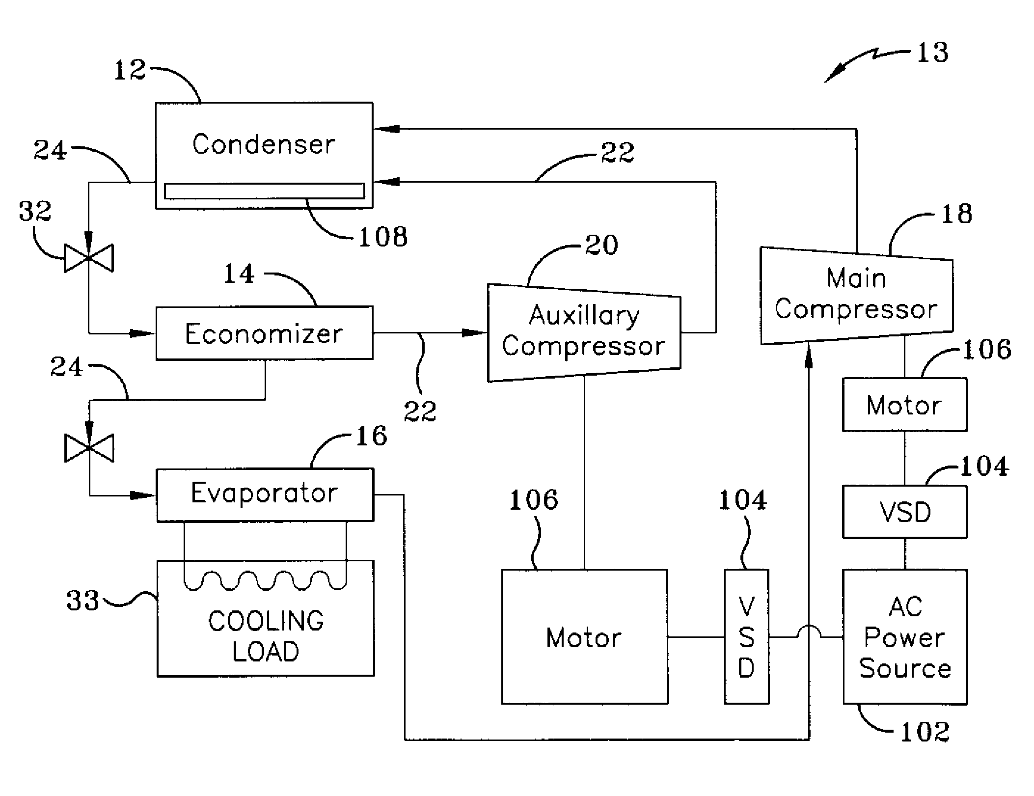
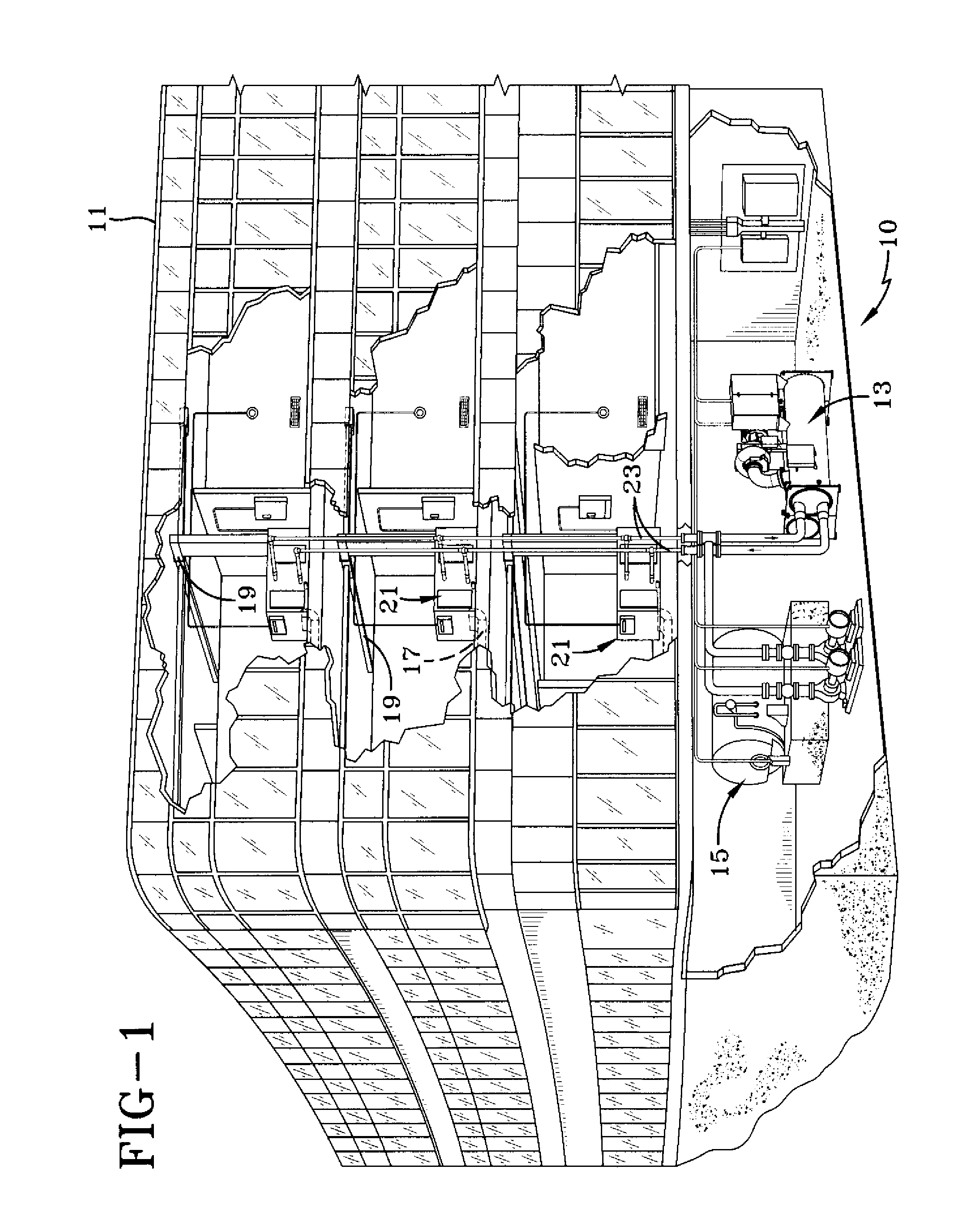
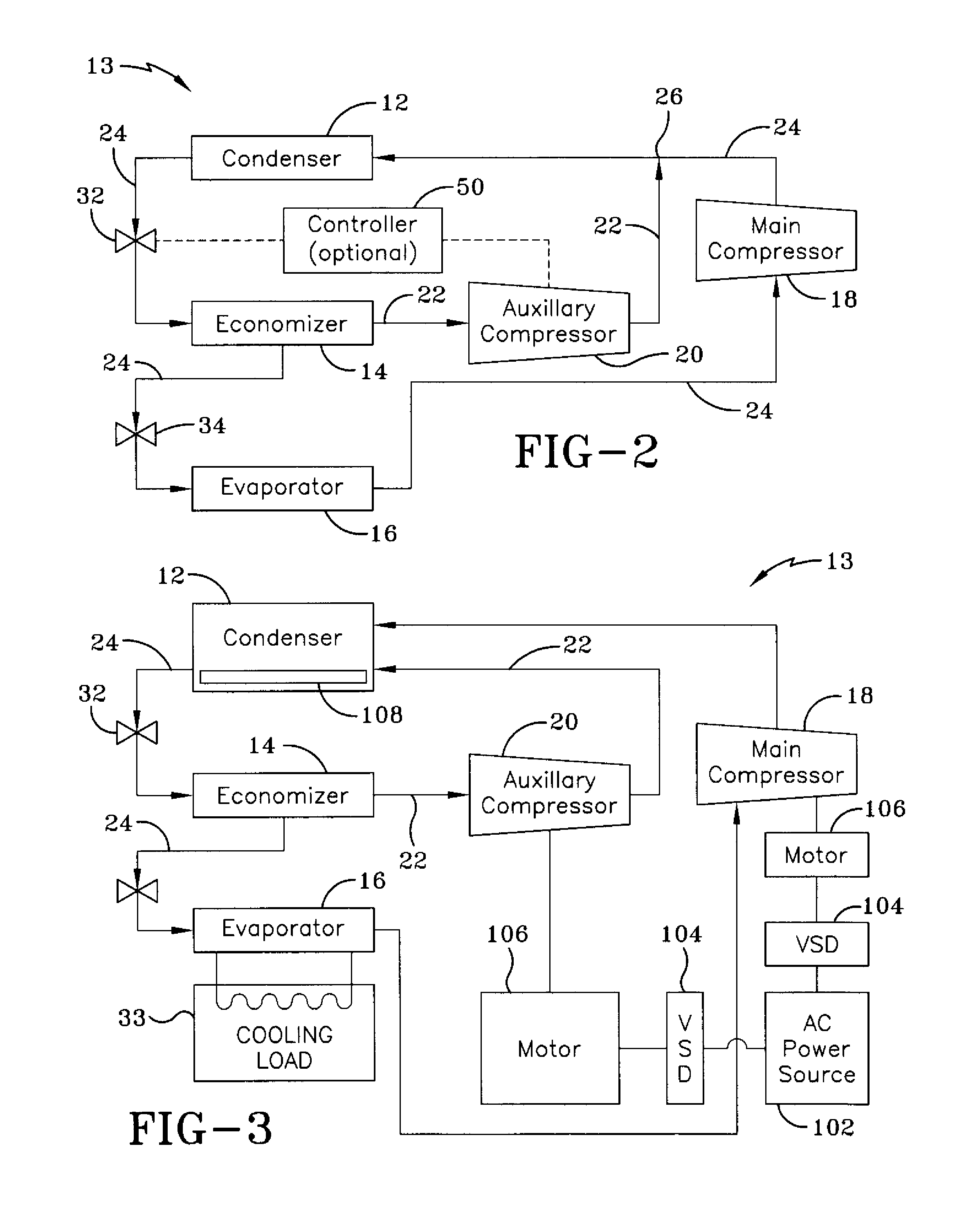
[0019]Referring to FIG. 1, an exemplary environment for a heating, ventilation, and air conditioning (HVAC) system 10 in a building 11 for a typical commercial setting is shown. HVAC system 10 may include a vapor compression system 13 incorporated into a basement unit that may supply a chilled liquid that may be used to cool building 11. HVAC system 10 may also include a boiler 15 to supply a heated liquid that may be used to heat building 11, and an air distribution system that circulates air through building 11. The air distribution system may include an air return duct 17, an air supply duct 19 and an air handler 21. Air handler 21 may include a heat exchanger (not shown) that is connected to boiler 15 and vapor compression system 13 by conduits 23. The heat exchanger in air handler 21 may receive either heated liquid from boiler 15 or chilled liquid from vapor compression system 13 depending on the mode of operation of HVAC system 10. HVAC system 10 is shown with a separate air ...


PUM


Abstract

A method and system for controlling operation of a vapor compression system (13) includes monitoring at least one component condition of the system (13), comparing a predetermined setpoint to the at least one component condition, and loading or unloading at least one of a first compressor (18) or a second compressor (20) of the system (13) in response to the comparison of the predetermined setpoint to the at least one component condition.

Description

CROSS-REFERENCE TO RELATED APPLICATIONS[0001]This application claims priority from and the benefit of U.S. Provisional Application No. 61 / 017,338, entitled ECONOMIZED VAPOR COMPRESSION SYSTEM, filed Dec. 28, 2007, which is hereby incorporated by reference.BACKGROUND[0002]The application generally relates to a vapor compression system. More specifically, the application relates to a system and method to control the intermediate pressure in an economized vapor compression system.[0003]A vapor compression system can include refrigerant gas compressed by a compressor and passed to a condenser where it exchanges heat with another fluid, for example, air or water, and is condensed to a liquid. From the condenser, the liquid refrigerant can pass through an expansion device and then to an evaporator, where the refrigerant exchanges heat with another fluid, for example, air or water, and is evaporated to a gas. The refrigerant gas can return to the compressor from the evaporator and the cycl...

Claims


Application Information

Patent Timeline
IPC IPC(8): F25B7/00F25D17/00
CPCF25B49/022F25B2341/0662F25B2400/075F25B2400/13F25B2400/16F25B2400/23F25B2600/0253F25B2700/21162F25B2700/21163F25B2700/21173F25B2700/21174Y02B30/741F25B41/39Y02B30/70
Inventor WELCH, ANDREW M.
Owner JOHNSON CONTROLS TYCO IP HLDG LLP
Why Eureka
Try Eureka