
Flexographic ink printing machine

a printing machine and flexographic technology, applied in printing presses, rotary letterpress machines, printing, etc., can solve the problems of difficult to obtain highly efficient supply and recovery of ink, halt the transferring operation of ink recovery tubings, and difficult to print machines, so as to prevent wear and tear, prolong the life of printing machines, and improve the adhesion condition of ink

Inactive Publication Date: 2006-02-16
ISOWA IND CO LTD
View PDF5 Cites 11 Cited by
  • Summary
  • Abstract
  • Description
  • Claims
  • Application Information

AI Technical Summary

Benefits of technology

[0018] said ink recovery tubings and said ink supply tubing have ink transfer means which can transfer the ink in both forward and backward directions between said ink supply source and said ink reservoir,
[0020] According to the printing machine disclosed above, during the printing operation, the ink within the ink reservoir is maintained in a dynamic state or circulated state by supplying the flexographic ink from the ink supply source to the ink reservoir via the ink supply tubing and by recovering the flexographic ink from the ink reservoir to the ink supply source via the ink recovery tubings, which allows the proper printing operation of the printing machine using the flexographic ink.
[0021] On the one hand, i.e., during ink supplying, the flowing direction of the ink flowing through the ink transfer means of the ink recovery tubings is reversed with respect to the flowing direction during a normal printing operation, in order to use the ink recovery tubings for supplying the ink from the ink supply source to the ink reservoir along with the ink supply tubing. Thus the efficiency of the ink supplying can be improved simply by changing the transferring direction of the ink transfer means, compared to the case in which only the ink supply tubing is used.
[0022] On the other hand, i.e., during ink recovering, the flowing direction of the ink flowing through the ink transfer means of the ink supply tubing is reversed with respect to the flowing direction during a normal printing operation, in order to use the ink supply tubing for recovering the ink from the ink reservoir to the ink supply source along with the ink recovery tubings. Thus the efficiency of the ink recovery can be improved simply by changing the transferring direction of the ink transfer means, compared to the case in which only the ink recovery tubings are used.
[0030] According to the printing machine disclosed above, by recovering the ink through the ink recovery tubings while the squeezing blades in the pair of squeezing blades moving toward the axial ends of the inking roller in the axial opposite directions, the ink adhering on the side surfaces of the inking roller and the ink squeezing member can be squeezed out, so that ink is directed into the remaining ink in the ink reservoir formed between squeezing blades and corresponding dam members, which raises the liquid level of the remaining ink in the ink reservoir, whereby allowing complete recovering of the ink.
[0031] At this time, water is removed from the ink reservoir in the portion between the pair of squeezing blades, which also causes the removal of the water contained within a number of indentations formed on the inking roller. However, at the same time, supplement water is supplied to the ink reservoir through the ink supply tubing located between the pair of squeezing blades, so as to supplement the water especially in the indentations of the inking roller, whereby allowing a good adhering condition of the ink during the printing operation, and preventing the causing of wear at the rotational contacting portion between the inking roller and the ink squeezing member, thus assuring a long life for the printing machine.

Problems solved by technology

However, there are several technical problems in such printing machines, especially during ink supplying for preparing the printing operation and during ink recovering after the printing operation has been completed.
The first problem is that, on the one hand, during ink supplying, ink is supplied from the ink supply source to the ink reservoir only using the ink supply tubing, during which the transferring operation of the ink recovery tubings is halted, in spite of there existing both the ink supply tubing and the ink recovery tubings for circulating the ink during the printing operation of the printing machine.
Therefore, according to the flexographic ink printing machine known in the art, which provides a proper printing operation by preventing the solidifying of the ink, it was difficult to obtain highly efficient supplying and recovering of the ink both during ink supplying for preparing the printing operation and during ink recovering after the printing operation has been completed.
The second problem is that, especially in the second type of the printing machine having a pair of dam members, it was difficult to completely recover the ink remaining in the ink reservoir, because the level of the ink in the ink reservoir drops down gradually during ink recovering, and because the ink reservoir has a cross section narrowly tapering toward its bottom.
This problem also arises when side surfaces of the pair of the rollers are being rinsed out by using rinsing water after the ink has been recovered.
The third problem is that, a recent trend in the art requires small lots of production, so the printing color must be quickly changed.
Thus it is difficult to remodel such a printing machine efficiently.

Method used


Image

  • Flexographic ink printing machine
  • Flexographic ink printing machine
  • Flexographic ink printing machine

Examples


Embodiment Construction

[0040] The flexographic ink printing machine of the preferred embodiment of the present invention is used for printing corrugated boards with flexographic ink.

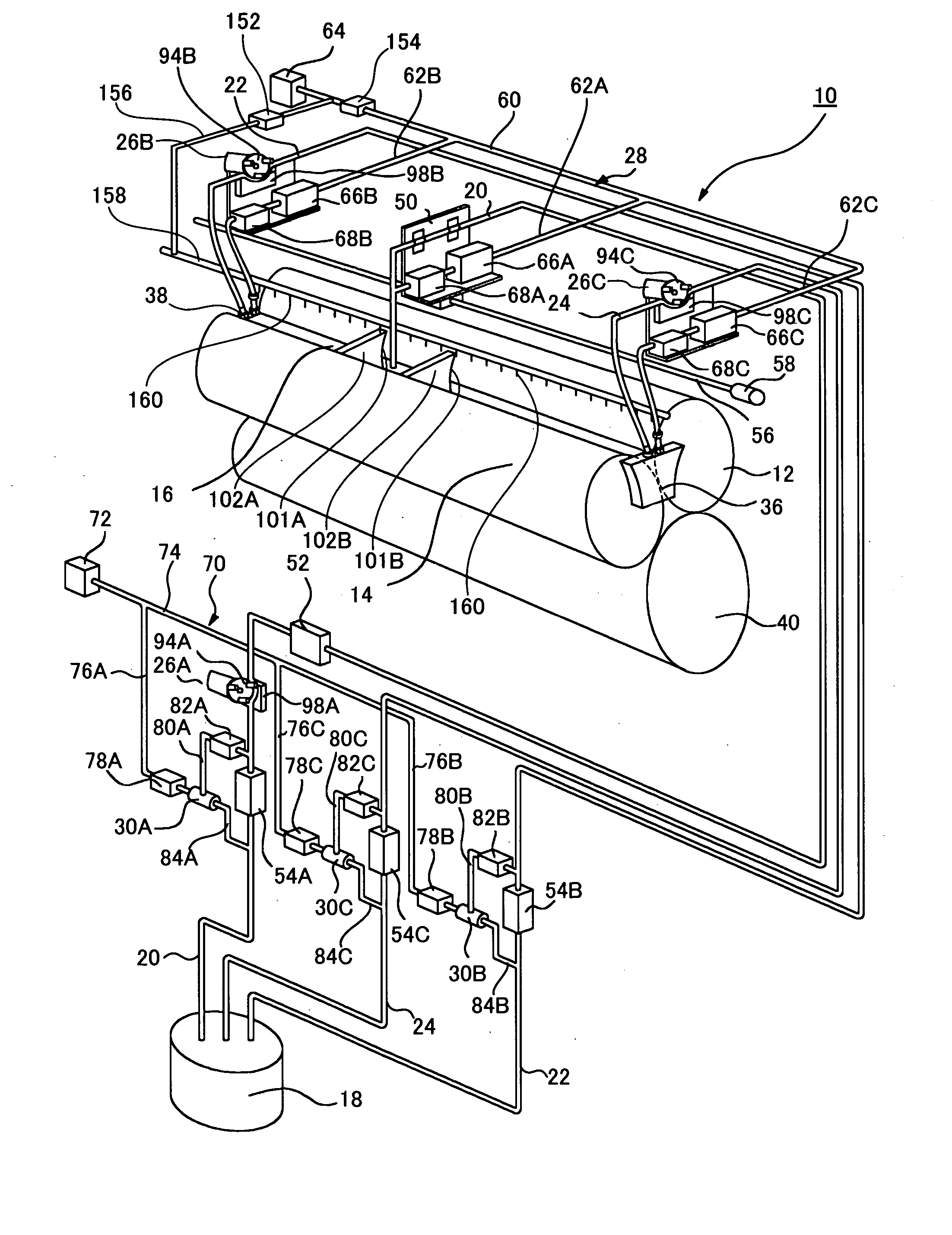
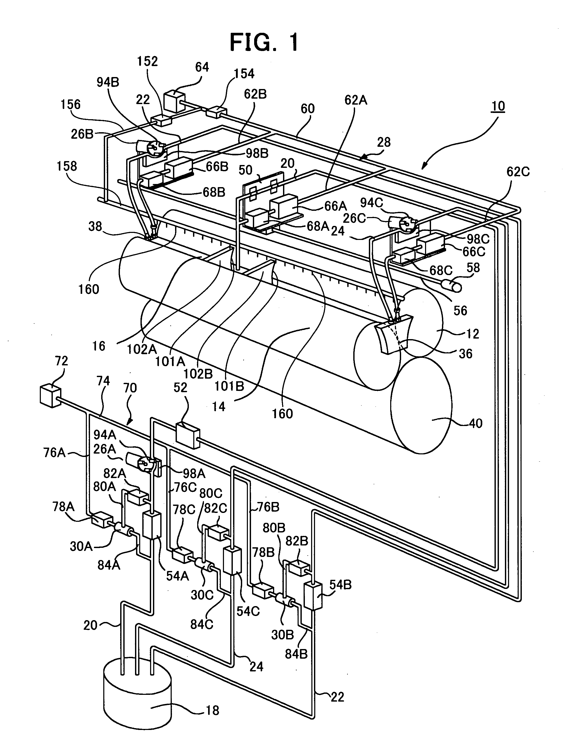
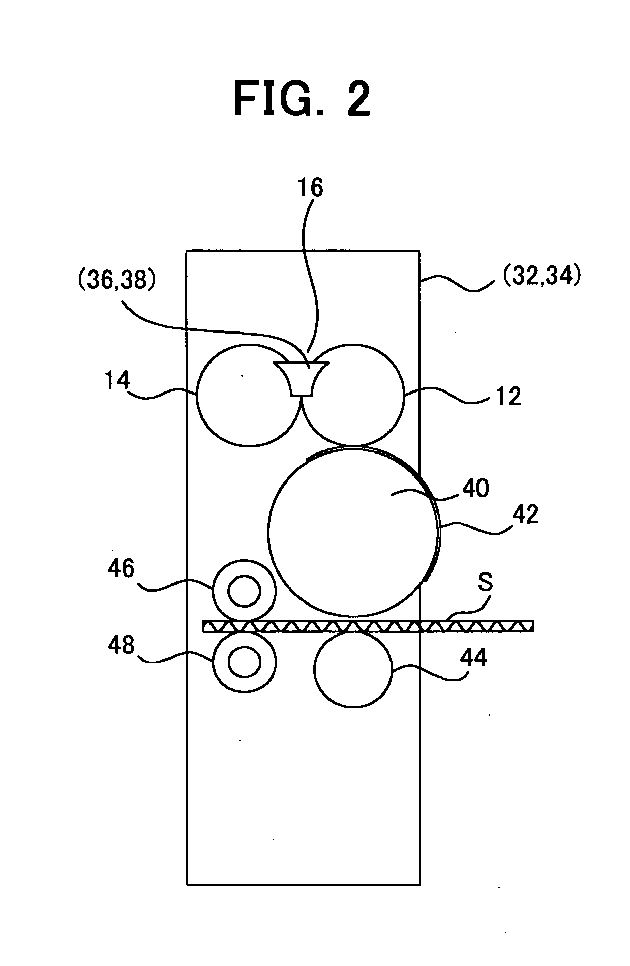
[0041]FIG. 1 is a perspective view showing a printing machine of the preferred embodiment of the present invention; FIG. 2 is a side elevational view showing a printing section of the printing machine illustrated in FIG. 1; FIG. 3 is a piping diagram showing relationships of various tubings and elements of the printing machine illustrated in FIG. 1; FIG. 4 is a side elevational view showing a pair of squeezing blades of the printing machine illustrated in FIG. 1; FIGS. 5A and B are a front view and a side view showing dam plates of the printing machine illustrated in FIG. 1; FIG. 6 is a schematic front view showing a tubing pump; and FIG. 7 is a schematic side view showing the tubing pump.

[0042] As can be seen in FIG. 1, the printing machine 10 includes an ink reservoir 16 formed by a pair of rollers 12 and 14, an ink supply...


PUM


Abstract

A flexographic ink printing machine is provided in which ink is circulated in order to prevent solidifying of the ink during a printing operation, whereby during ink supplying or ink recovering operations, high efficiency of supplying and recovering the ink can be obtained. A printing machine which includes an ink reservoir, an ink supply source, and ink delivery tubings each connecting said ink reservoir to said ink supply source, whereby the ink supplied from said ink supply source via at least one of said ink delivery tubings to said ink reservoir and accumulated therein is used for printing, said ink delivery tubings including ink recovery tubings for recovering the flexographic ink from said ink reservoir to said ink supply source, said ink recovery tubings having their ink recovery opening ends located within said ink reservoir, said ink delivery tubings including ink supply tubing for supplying the flexographic ink from said ink supply source to said ink reservoir, said ink supply tubing having its ink supply opening end located within said ink reservoir, whereby the ink within said ink reservoir is maintained in a dynamic state by supplying said flexographic ink from said ink supply source to said ink reservoir via said ink supply tubing and by recovering the flexographic ink from said ink reservoir to said ink supply source via said ink recovery tubings during the printing operation of the printing machine, wherein: said ink recovery tubings and said ink supply tubing have ink transfer means which can transfer the ink in both forward and backward directions between said ink supply source and said ink reservoir, wherein the flexographic ink is recovered from said ink reservoir to said ink supply source via said ink recovery tubings and said ink supply tubing now being used as an ink recovery tubing during ink recovering, and wherein the flexographic ink is supplied from said ink supply source to said ink reservoir via said ink supply tubing and said ink recovery tubings now being used as ink supply tubings during ink supplying.

Description

FIELD OF THE INVENTION [0001] The present invention relates to a printing machine using flexographic ink, more particularly, to a flexographic ink printing machine in which solidifying of the ink can be prevented during a printing operation, whereby during ink supplying or during ink recovering, highly efficient supplying and recovering of the ink can be obtained. BACKGROUND OF THE INVENTION [0002] Conventionally, when a printing machine prints a sheet of paper, such as a corrugated board with flexographic ink, it is common to press a printing die having ink applied thereon against the surface of a sheet. These printing machines, such as disclosed in Japanese patent document S55-45,568(U) and S60-119,539(U), usually include a pair of rollers, one of which supports the printing die on the outer surface thereof, an ink reservoir formed between said roller and another roller engaging therewith, an ink supply source, and a ink supply tubing and ink recovery tubings each connected betwee...

Claims


Application Information

Patent Timeline
IPC IPC(8): B41F31/02B41F31/08
CPCB41F5/24B41F31/08B41F31/025
Inventor WATANABE, HIROMIADACHI, NOKIHISA
Owner ISOWA IND CO LTD
Learn More