Hydro-mechanically coupled electric power steering system

a technology of electric power steering and mechanical coupling, which is applied in the direction of power steering, vehicle components, fluid steering, etc., can solve the problems of fluid pressure spike that is transmitted to the steering wheel, undesirable impulse to the steering wheel of the host vehicle, etc., and achieve the effect of improving the steering feel

Inactive Publication Date: 2006-02-16
TECHCO +1
View PDF43 Cites 8 Cited by
  • Summary
  • Abstract
  • Description
  • Claims
  • Application Information

AI Technical Summary

Benefits of technology

The present invention is a hydro-mechanically coupled power steering system that improves the feel of steering in situations where minimal power assist is required. It decouples the power cylinder from the pump when the steering wheel torque is low, reducing the reflected motor inertia from the system. The system also includes a solenoid-controlled valve apparatus and check valves to accommodate reversals of differential pressure polarity and improve fresh fluid replenishment. The system controller issues motor-controlling and solenoid-controlling signals to the pump based on the applied torque signal and fluid pressure present in the first and second fluid lines. The system is controlled in a fail-safe mode in the event of an unexpected system fault. Overall, the invention provides better steering feel and improved control of the power steering system.

Problems solved by technology

This may be made worse because the motor inertia is compliantly coupled to the steering wheel via a compliant member such as a torsion bar.
This is a problem because the hydraulically coupled EPS system described in the '254 patent includes a two-position, three-way (shuttle) valve utilized for the purpose of coupling the lower pressure ports of the pump and power cylinder to system reservoir pressure.
It has been found that provision of even the small amount of fluid required for displacing the two position, three-way shuttle valve can result in an undesirable impulse to the host vehicle's steering wheel whenever there is a substantial on-center pressure offset.
This results in a fluid pressure spike that is transmitted to the steering wheel via the power cylinder, rack-and-pinion interface, and steering shaft.

Method used


Image

  • Hydro-mechanically coupled electric power steering system
  • Hydro-mechanically coupled electric power steering system
  • Hydro-mechanically coupled electric power steering system

Examples


Embodiment Construction

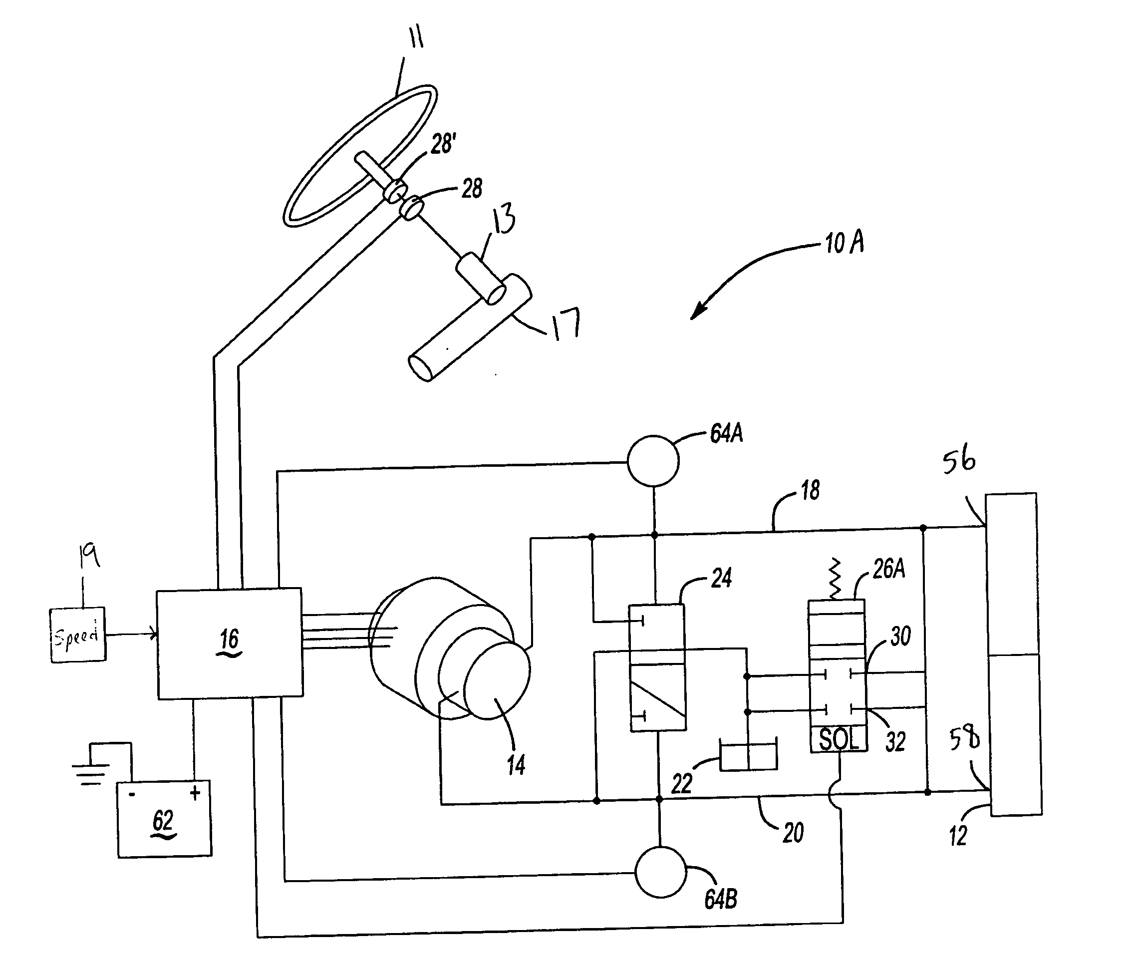
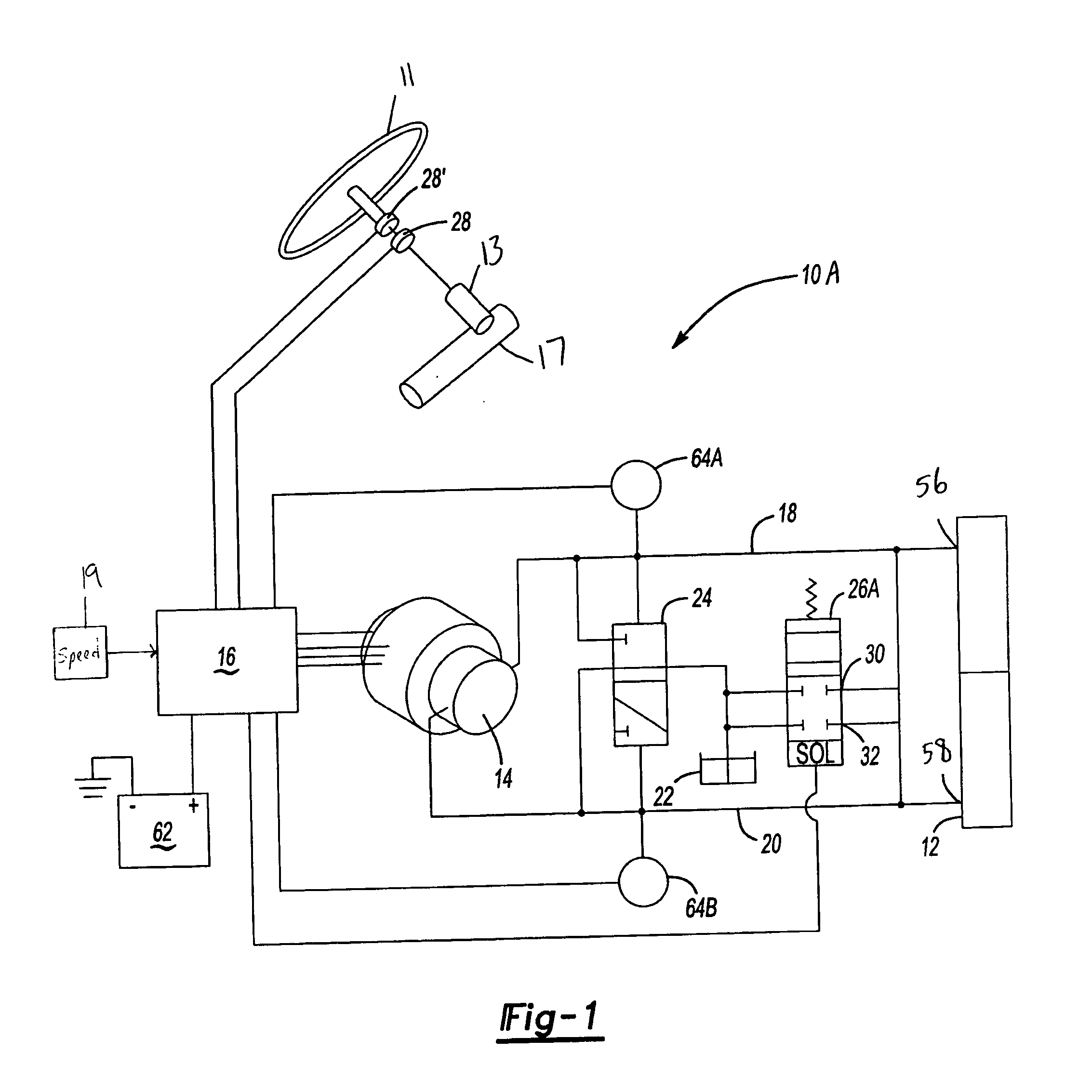
[0016] One example of a hydro-mechanically coupled power steering system 10A is shown schematically in FIG. 1. FIG. 1 depicts most of the elements of the hydro-mechanically coupled power steering system of the '254 patent. A steering wheel 11 is connected to the steerable wheels (not shown) by a suitable steering gear 13 engaged (directly or indirectly) with a gear rack 17. A torque sensor 28 is connected to the steering wheel 11 and generates an electrical or electronic signal representative of the magnitude and direction of a steering torque applied to the steering wheel 11. A secondary torque sensor 28′ provides a redundant torque signal utilized in a fail-safe function for the power steering system 10A. The application of an applied steering torque to the steering wheel 11, as sensed by the torque sensor 28, results in the application by the power steering system 10A of an assisted steering force to the steerable wheels.

[0017] The power steering system 10A includes a power cyli...


PUM


Abstract

A power steering system provides improved steering feel whenever negligible power assist is required is required such as during on-center operation or at very high vehicular speeds. The power steering system includes fluid lines used for directly coupling a motor driven pump to a power cylinder. The fluid lines are coupled to a system reservoir or to one another whenever a primary control signal indicative of steering wheel torque has a value below a selected threshold value thereby substantially decoupling the power cylinder from the pump.

Description

[0001] This application claims priority to U.S. Provisional Application Ser. Nos. 60 / 602,027, filed Aug. 16, 2004 and 60 / 672,387, filed Apr. 18, 2005.BACKGROUND OF THE INVENTION [0002] The present invention relates generally to power steering systems for vehicles, and more particularly to hydro-mechanically coupled electrically powered steering systems. [0003] Currently it is anticipated that an overwhelming majority of vehicular power steering systems will be electrically powered in the future. Most common will be electric power steering systems (hereinafter “EPS systems”) wherein motors deliver torque as a function of current applied to them by a controller. One example is described in U.S. Pat. No. 6,152,254, entitled “Feedback and Servo Control for Electric Power Steering System with Hydraulic Transmission,” issued Nov. 28, 2000, which is hereby incorporated by reference in its entirety. In that EPS system differential pressure is directly delivered to a double-acting power cyli...

Claims


Application Information

Patent Timeline
Patent Type & Authority Applications(United States)
IPC IPC(8): B62D5/06
CPCB62D5/064B62D6/08B62D5/065
Inventor PHILLIPS, EDWARD H.
Owner TECHCO
Why Eureka
Try Eureka