Outboard motor steering system

a steering system and motor technology, applied in the direction of steering rudders, steering by propulsive elements, vessel construction, etc., can solve the problems of complex structure, disadvantages of human-powered steering systems, and unpleasant steering “feels”

Inactive Publication Date: 2006-11-14
HONDA MOTOR CO LTD
View PDF13 Cites 3 Cited by
  • Summary
  • Abstract
  • Description
  • Claims
  • Application Information

AI Technical Summary

Benefits of technology

[0010]An object of the present invention is therefore to overcome the foregoing issues by providing an outboard motor steering system that improves steering feel, is simply configured to avoid increase in number of components and weight, and does cause a problem regarding space utilization.
[0011]An object of the present invention is therefore to overcome the foregoing issues by providing an outboard motor steering system that improves steering feel, is simply configured to avoid increase in number of components and weight, and does not cause a problem regarding space utilization.
[0012]Another object of the present invention is therefore to provide an outboard motor steering system that is configured in common with a hydraulic system for the power tilt-trim system to make it unnecessary to equip the steering system with a dedicated hydraulic pump and power source therefor, thereby enabling to reduce in size and weight.

Problems solved by technology

Human-powered steering systems are disadvantageous because they tend to have an unpleasant steering “feel” owing to, for instance, heavy steering load.
The add-on steering system using a hydraulic cylinder also has disadvantages, most notably that its structure is complicated, that it adds to the number and weight of the components, and that it takes up space between the front of the outboard motor and the rear of the boat.
However, the steering system taught by '495 is disadvantageous from the aspect of saving space around the outboard motor because in some operating states of the hydraulic cylinder, the hydraulic cylinder projects from the outboard motor main unit.

Method used


Image

  • Outboard motor steering system
  • Outboard motor steering system
  • Outboard motor steering system

Examples


second embodiment

[0064]An outboard motor steering system according to the invention will now be explained with reference to FIGS. 6 and 7.

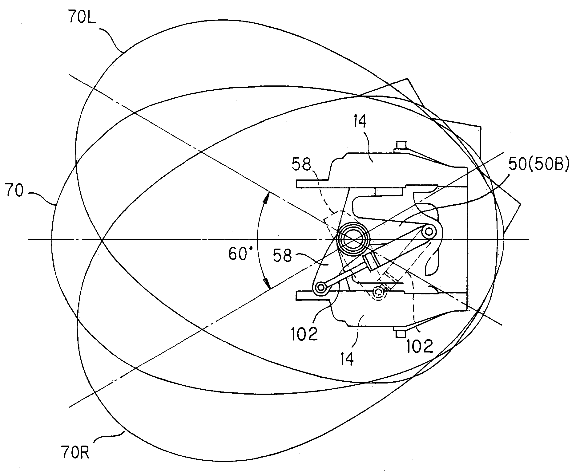
[0065]FIG. 6 is a partial explanatory side view showing the outboard motor steering system according to the second embodiment. FIG. 7 is an explanatory view from below (looking upward in the gravitational direction) showing the electric motor 42, swivel case 50 and lower mount center housing 58. The power tilt-trim unit 44 is omitted from FIG. 6 for simplicity of illustration.

[0066]The points of difference from the embodiment set out in the foregoing will be explained. As shown in FIGS. 6 and 7, in this embodiment the electric motor 42 is fastened to a lower portion 50B of the swivel case 50 inside the outboard motor 10 (within the vertical projection plane 70 of the profile of the outboard motor main unit).

[0067]An output shaft gear 42b fastened on the output shaft of the electric motor 42 meshes directly with a larger-diameter lower mount center housing gear 58a...

third embodiment

[0072]An outboard motor steering system according to the invention will now be explained with reference to FIG. 8.

[0073]FIG. 8 is an explanatory perspective view showing the outboard motor steering system according to a third embodiment of the invention.

[0074]The points of difference from the embodiments set out in the foregoing will be explained. In this embodiment, as shown in FIG. 8, an output shaft reel gear 42a1 is fastened on the output shaft of the electric motor 42 and a swivel shaft reel gear 54a is fastened on the swivel shaft 54 near where it is joined to the mount frame 56.

[0075]A cable 90 equipped with a holder is wrapped around the output shaft reel gear 42a1 and swivel shaft reel gear 54a to interconnect them by meshing of the cable with the reel gears. The output of the electric motor 42 is transmitted to the swivel shaft 54 by pushing and pulling the cable 90.

[0076]Specifically, the rotational output of the electric motor 42 rotates the swivel shaft 54 by advancing ...

fourth embodiment

[0080]An outboard motor steering system according to the present invention will now be explained with reference to FIGS. 9 to 19.

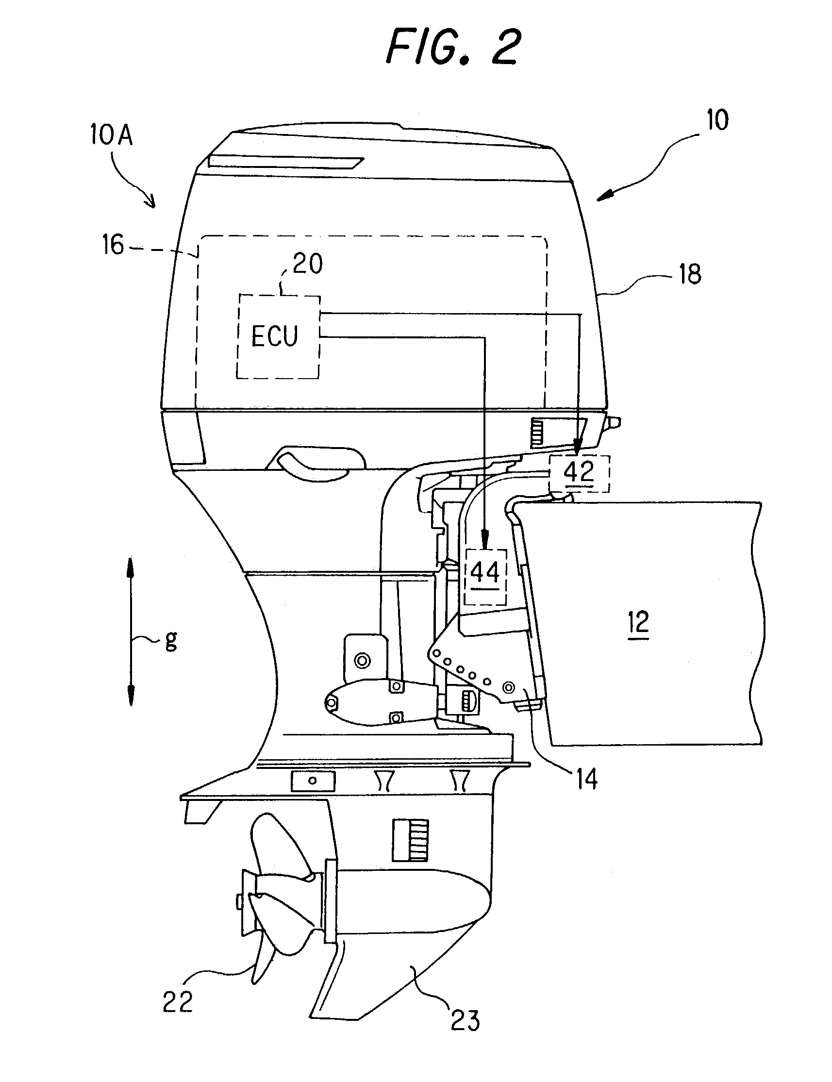
[0081]FIG. 9 is a partial explanatory side view similar to FIG. 2 showing the outboard motor steering system according to the fourth embodiment.

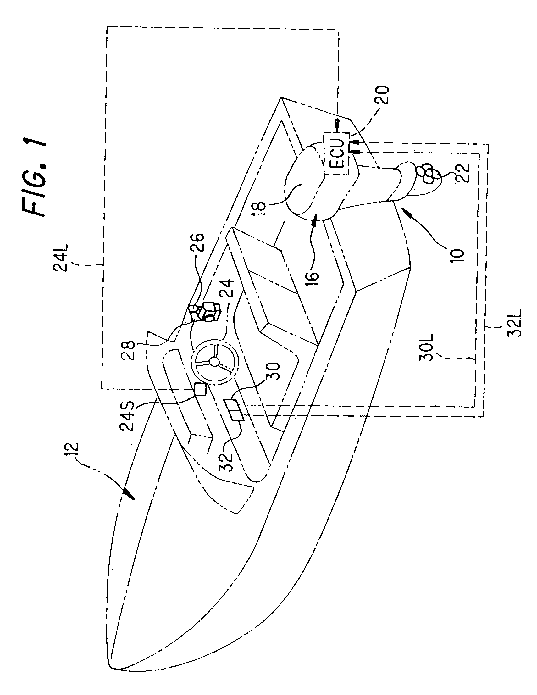
[0082]The points of difference from the embodiments set out in the foregoing will be explained. In this embodiment, the ECU 20 is configured to operate a hydraulic cylinder unit 100 in accordance with the output of the steering angle sensor 24S received via the signal line 24L and the outputs of the power tilt switch 30 and power trim switch 32 received via the signal lines 30L and 32L.

[0083]FIG. 10 is an enlargement of the explanatory side view of FIG. 9. FIG. 11 is an enlarged front view of the hydraulic cylinder unit 100 seen from the side of the boat 12.

[0084]As shown in FIGS. 10 and 11, the hydraulic cylinder unit 100 is integrally configured by interconnecting a steering hydraulic cylinder 102 and the aforesa...


PUM


Abstract

A steering system of an outboard motor is provided that is mounted on a stern of a boat and having an internal combustion engine at its upper portion and a propeller with a rudder at its lower portion that is powered by the engine to propel the boat. The steering system includes a cowl enclosing the engine and a hydraulic cylinder connected to the outboard motor at one end and to the boat at other end to swivel the outboard motor relative to the boat to steer the cowl, the propeller, and the engine about a vertical axis. The hydraulic cylinder is located inside a vertical plane of a profile of the outboard motor when viewed along the vertical axis such that the hydraulic cylinder never projects outside the profile in any steered position of the motor.

Description

BACKGROUND OF THE INVENTION[0001]1. Field of the Invention[0002]This invention relates to an outboard motor steering system.[0003]2. Description of the Related Art[0004]Almost all outboard motor steering systems have up to now been of types operated by human power, such as the tiller handle type used to turn the rudder by manually operating a tiller handle attached to the outboard motor and the remote control type used to remotely operate a steering mechanism through a push-pull cable. Further, an add-on mechanism constituted as a separate unit from the outboard motor and used to power-assist the turning of the tiller handle is known. As shown in FIG. 23, this mechanism typically includes a steering hydraulic cylinder 204 attached to the front (boat side) of an outboard motor 200 through stays 202, and a link mechanism 206 connected between the hydraulic cylinder 204 and a tiller handle 208.[0005]Human-powered steering systems are disadvantageous because they tend to have an unpleas...

Claims


Application Information

Patent Timeline
Patent Type & Authority Patents(United States)
IPC IPC(8): B63H20/08B63H25/42B63H20/10B63H20/12B63H25/26B63H25/30
CPCB63H20/08B63H20/10B63H20/12B63H25/26B63H25/30
Inventor TAKADA, HIDEAKIMIZUGUCHI, HIROSHIWATABE, HIROSHIMASUBUCHI, YOSHINORIOTOBE, TAIICHI
Owner HONDA MOTOR CO LTD
Why Eureka
Try Eureka