USB battery charger

a technology of usb battery and charger, which is applied in the direction of electric power, electric vehicles, transportation and packaging, etc., to achieve the effects of reducing vbus, reducing charge current, and reducing vbus

Inactive Publication Date: 2006-02-16
ADVANCED ANALOGIC TECHNOLOGIES INCORPORATED
View PDF4 Cites 53 Cited by
  • Summary
  • Abstract
  • Description
  • Claims
  • Application Information

AI Technical Summary

Benefits of technology

[0006] The present invention includes a USB battery charger. The battery charger is typically deployed within a USB device and is positioned to control the flow of current between the USB host and a battery that is also included in the USB device. Depending on the state of the battery, the charger operates in one of three modes: trickle charging, fast charging and voltage regulation. During trickle charging, the charger sends a preset trickle charge current to the battery as long as the battery voltage is below a normal level. Once the battery reaches the normal level, fast charging is initiated with a preset high charge current (assuming, again that the voltage of the USB VBUS circuit can be maintained). In fast charge mode, the charge current is regulated as long as the USB bus voltage (VBUS) can support it. When the USB becomes incapable of supplying the preset charge current, VBUS drops. At that point, a “charge reduction loop” within the battery charger reduces the charge current to maintain VBUS. In this way, the charge current is maximized to the extent possible without reducing VBUS. The VBUS triggering point can be set by the user with a resistor divider.

Problems solved by technology

When the USB becomes incapable of supplying the preset charge current, VBUS drops.

Method used


Image

  • USB battery charger

Examples


Embodiment Construction

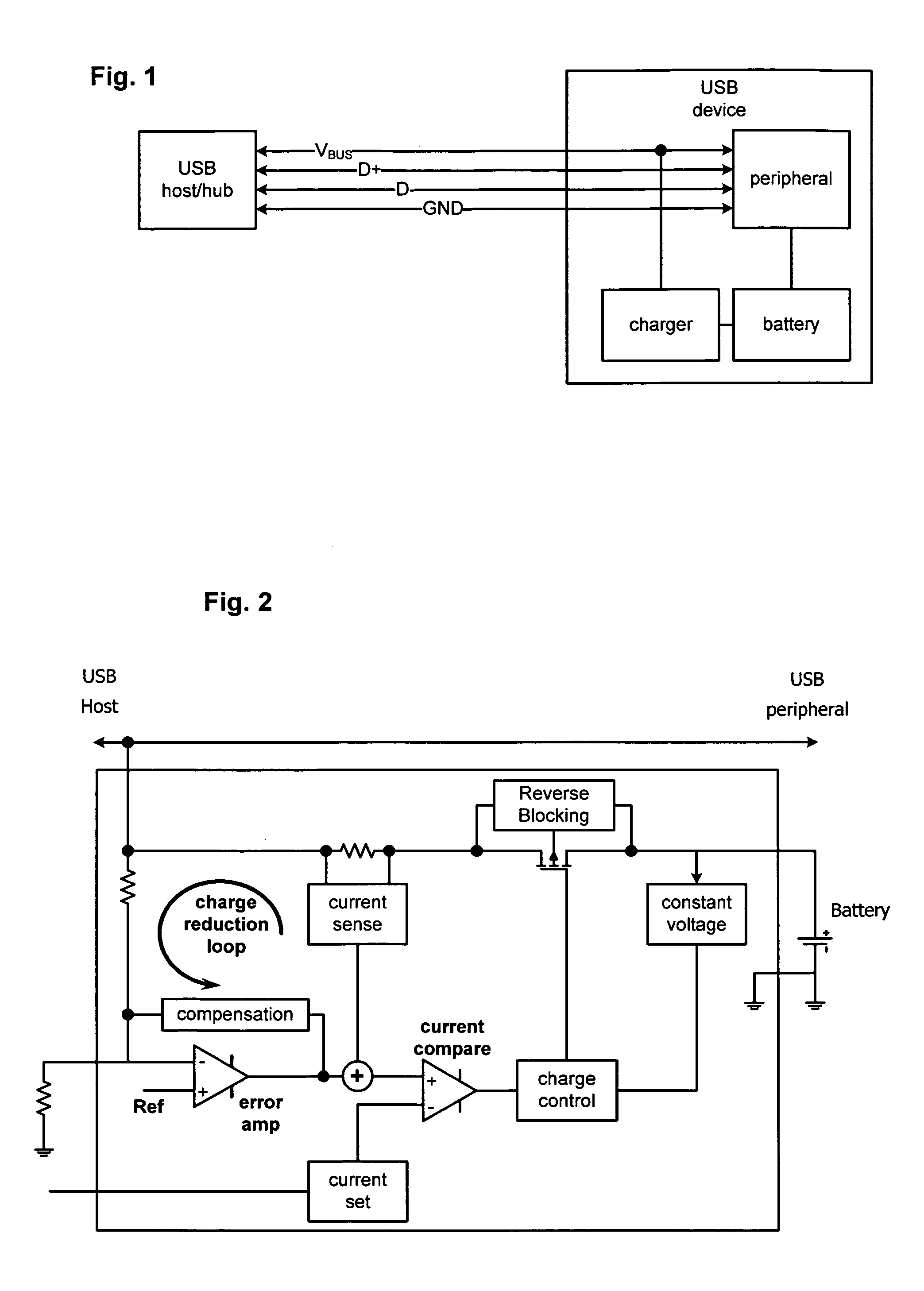
[0009] The present invention includes a charger for batteries in USB devices. As shown in FIG. 1, the charger is typically included, along with a battery, as part of a USB device. In most cases (but not in all cases) the USB device would also include some other functional block such as a cellular telephone or personal music player. In FIG. 1, this functional block is generically labeled “USB peripheral.” The charger is powered by a USB host via the USB VBUS circuit. The VBUS circuit is also typically used to power the USB peripheral. The charger uses power from the USB VBUS circuit to charge the battery enabling operation of the USB device when disconnected from the USB host (or hub).

[0010] One possible implementation for the USB charger is shown in FIG. 2. As shown in that figure, the charger includes a path for current to flow from the USB VBUS circuit to the battery. The path includes a current sense resistor and a transistor. In this case, the transistor is a MOSFET, but there ...


PUM


Abstract

A USB battery includes a transistor that controls the flow of current between a USB host and a battery. The transistor is controlled a function of: 1) the amount of current flowing to the battery, and 2) the voltage on the USB VBUS circuit. The transistor dynamically regulates the amount of trickle current to approach a predetermined maximum as closely as practical while maintaining the voltage on the VBUS circuit above a predetermined minimum.

Description

TECHNICAL FIELD OF THE INVENTION [0001] The present invention relates generally to portable electronic devices. More particularly, the present invention relates to devices for charging batteries using power supplied by a universal serial bus. BACKGROUND OF THE INVENTION [0002] In recent years, the universal serial bus (USB) has become one of the most widely used methods for interconnecting electronic devices. Originally used to interconnect computers and standard peripheral devices (such as disk drives), deployment of USB has grown to support a vast array of devices including cellular telephones, cameras and personal music players. [0003] Logically, USB systems have an inverted tree-like structure. At top of the tree (i.e., at the root since the tree is inverted) is the USB host. Up to seven USB devices may be connected directly to the USB host. In cases where more than seven devices are required, a USB hub may be used. Each USB hub may be further connected to its own set of seven U...

Claims


Application Information

Patent Timeline
Patent Type & Authority Applications(United States)
IPC IPC(8): H02J7/00
CPCH02J7/045H02J7/04H02J7/00714H02J7/007182
Inventor SHUM, KIN EDWARD
Owner ADVANCED ANALOGIC TECHNOLOGIES INCORPORATED
Why Eureka
Try Eureka